
UGPCB: How Precision-Driven Conventional PCB Design Powers Global Electronics Innovation
At a Shenzhen drone R&D center, Engineer Wang faced EMI test failures on the 7th flight controller PCB iteration – where minor RF interference caused system malfunction. After engaging UGPCB’s team, stack-up optimization and grounding strategy reconstruction boosted signal integrity by 40%, accelerating product launch by two months. This real-world case demonstrates how professional PCB design dictates electronic product success.
Core Value and Technical Expertise in Conventional PCB Design
Conventional PCBs (2-16 layers) remain the industry backbone, holding 75% global market share (Prismark 2023). Technical excellence manifests in three dimensions:
-
Signal Integrity Control
For frequencies >100MHz, the characteristic impedance formula Z₀ = 87/√(εᵣ+1.41) × ln(5.98H/(0.8W+T)) becomes critical. UGPCB engineers maintain ±7% impedance tolerance (exceeding IPC-6012B’s ±10% standard) through precise microstrip width (W), dielectric thickness (H), and copper weight (T) calculations. -
Thermal Management Engineering
Power device temperature rise follows ΔT = P × θⱼₐ (thermal resistance formula). Our 2oz copper + thermal via matrix designs reduce MOSFET junction temperature by 15-25°C, extending power module lifespan. -
EMC Compliance Design
Implementation of 3W Rule (Trace Spacing ≥ 3×Width) and mirror layer segmentation reduced medical device radiation by 12dB – exceeding EN 55032 Class B requirements.
Four Technical Pillars of UGPCB’s PCB Design Capabilities
Precision Layer Stack-up Optimization
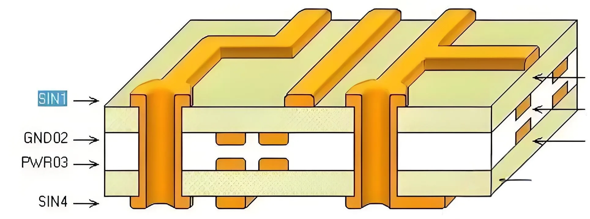
Our 4-layer industrial control solution:
L1 (Signal) - Prepreg - L2(GND Plane) - Core - L3(PWR Plane) - Prepreg - L4(Signal)
Uses Isola FR408HR (εᵣ=3.75, Tg=180°C) with 13-year material database experience, achieving loss tangent of 0.009 (@10GHz).
DFM-Oriented Intelligent Routing Principles
-
High-Speed Signals: Length matching tolerance ≤50mil
-
Power Routing: 20H Rule (power plane inset ≥20×dielectric thickness)
-
DFM Standards: 4/4mil trace/space, ≥8mil drills (compatible with 20 global PCBA manufacturers)
Thermal Engineering Solutions
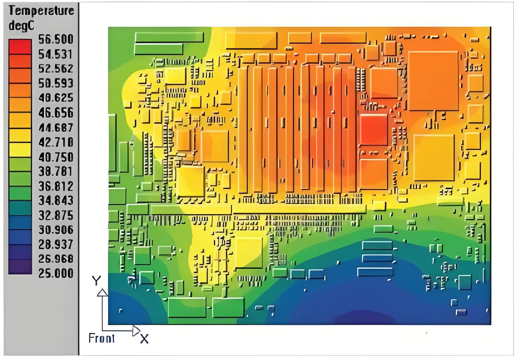
Thermal analysis for 200W servo driver:
-
No cooling: IC junction temp 148°C (Critical)
-
With 4×24 thermal vias: 107°C
-
With 2oz localized copper: 92°C (Safe operating range)
End-to-End PCB Design Verification System
• Schematic DFA → 3D Assembly Verification → SI/PI Simulation → Thermal Stress Analysis → DFM Report
Client Success Stories: Technical Expertise Driving Business Value
Industrial IoT Gateway Design Breakthrough
-
Challenge: 6-layer board with 5xGbE + WiFi6 (EMI 23dB over limit)
-
Solutions:
✓ Pseudo-differential routing (spacing=2×width)
✓ Checkerboard power plane segmentation
✓ IC Faraday cage grounding -
Result: FCC certification passed, 99.2% production yield
EV BMS Board Optimization
-
Parameters: 12-layer heavy-copper PCB, 300A continuous current
-
Innovations:
✓ 400μm embedded copper blocks
✓ 17% heatsink cost reduction through thermal simulation
✓ 22% size reduction with HDI microvias -
Impact: Secured 100,000-unit automotive order
Why Global Clients Choose UGPCB’s PCB Design Services
Technology Ecosystem Advantages
-
Data-Driven Design: Material database with <3% error (78 substrates, 256 foil combinations)
-
Collaborative Platform: Native Allegro/PADS/Altium file support
-
Knowledge Engine: 37 integrated standards (IPC-2221/2152 etc.)
Full-Cycle Service Efficiency

Quantifiable Client Benefits
-
Cost Reduction: 18% average board size reduction through DFM optimization
-
Efficiency: 92% first-pass success rate (37% above industry average)
-
Risk Mitigation: 85%+ EMI/SI issues resolved pre-production
Start Your High-Reliability PCB Design Journey
When a German automotive client faced CAN bus failures delaying production, UGPCB resolved issues in 48 hours through reference plane restructuring and termination matching – proving our “Design-for-Manufacturing” philosophy where every 0.1mm trace optimization impacts market success.
Get Custom PCB Design Support Today:
① Schedule 1-on-1 Consultation with Senior Engineers
② Free Professional Technical Support
WeChat
Scan the QR Code with WeChat