Im Prozess der PCBA-Oberflächenmontage, Verschiedene elektronische Komponenten fallen häufig aus. Heute, Wir teilen eine Fallstudie zur Fehleranalyse eines 3A-Linearreglers, Erklären, wie man über den Tellerrand schaut und den Fehler schnell erkennt.
1) Beschreibung des Chipversagens: Vin ist kurzverkauft zu Masse.
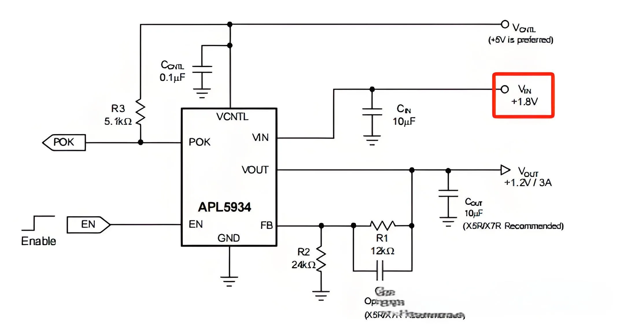
Vin ist kurzverkauft zu Masse.
2) Geräteausfallanalyse: Der Chip erlebte ein EOS (Elektrischer überstresstes) Versagen, wie durch IV-Tests mit Vin-Kurzschluss zur Erde bestätigt.
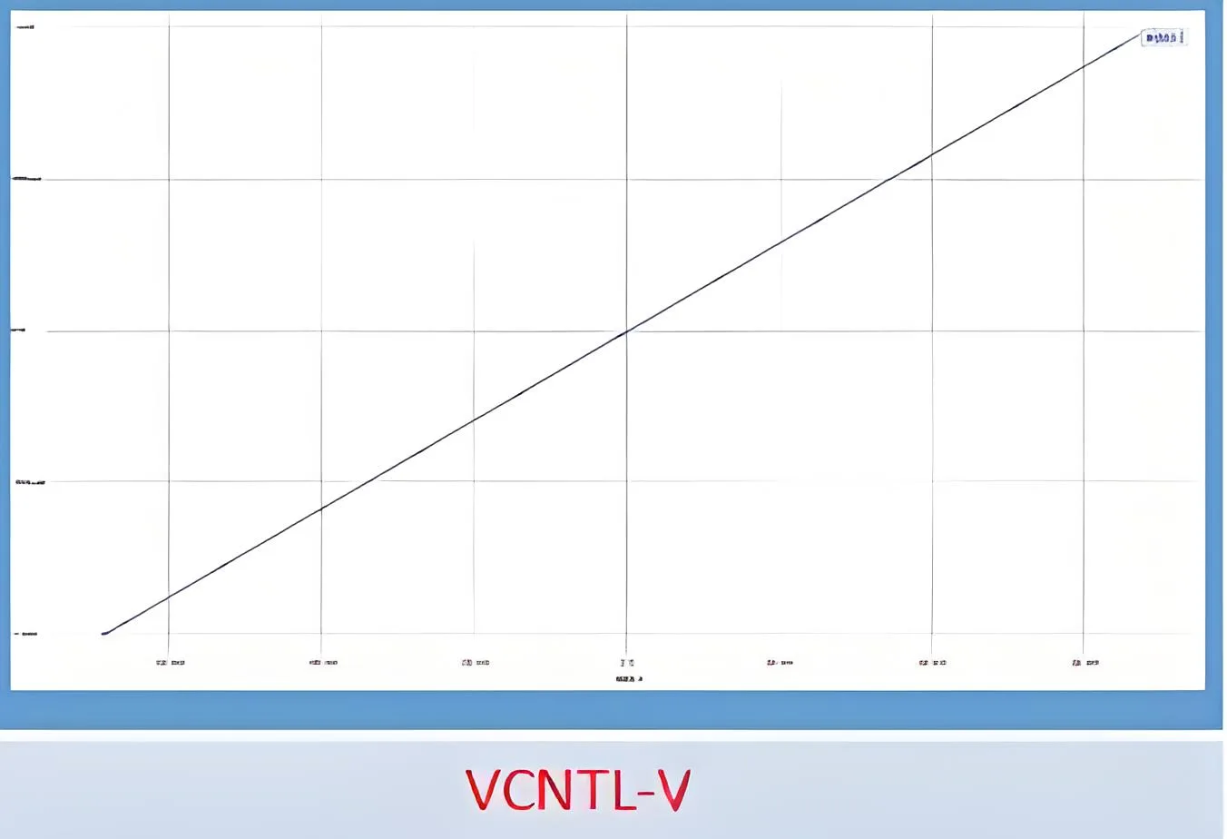
Der IV -Test bestätigt Vin, der Kurzschluss ermorscht hat.
Es wurden keine offensichtlichen Anomalien beim Aussehen oder beim akustischen Scannen beobachtet, Aber Röntgenaufnahmen zeigten mutmaßliche Verbrennungsschäden.
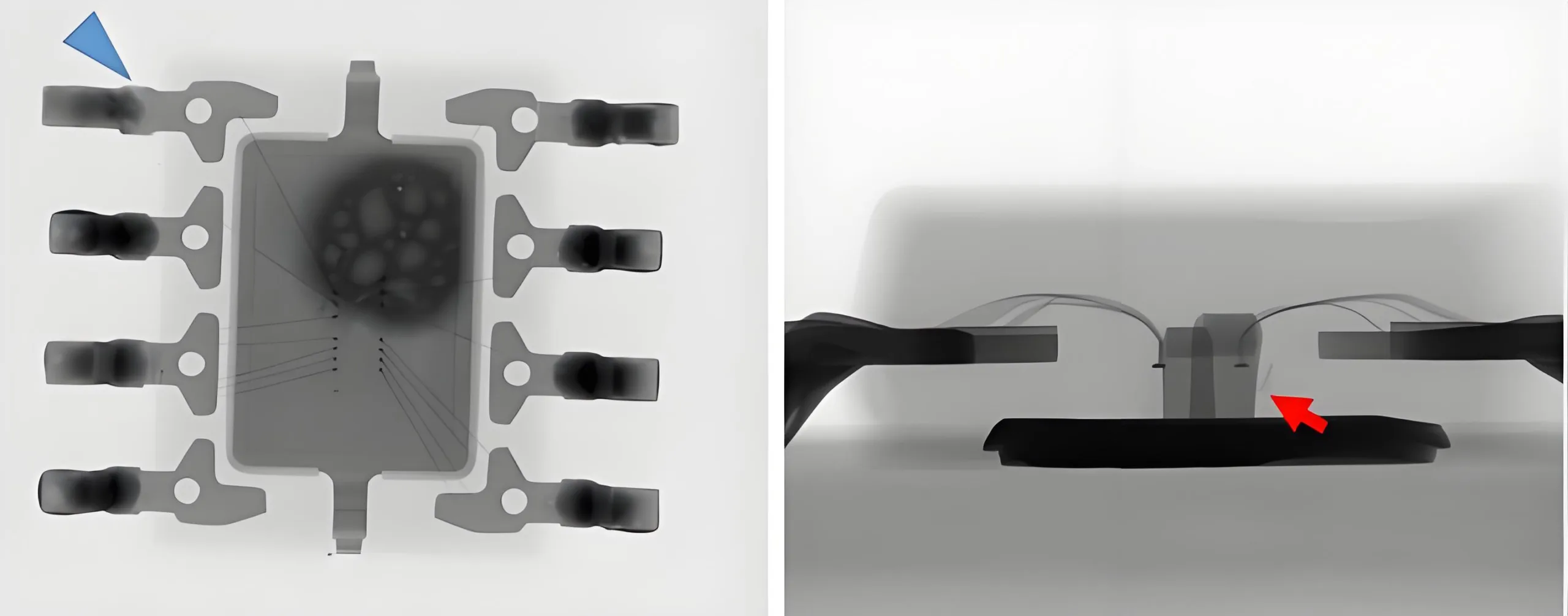
Verdacht, verbrannt worden zu sein
Beim Öffnen der Abdeckung, Es wurde festgestellt.
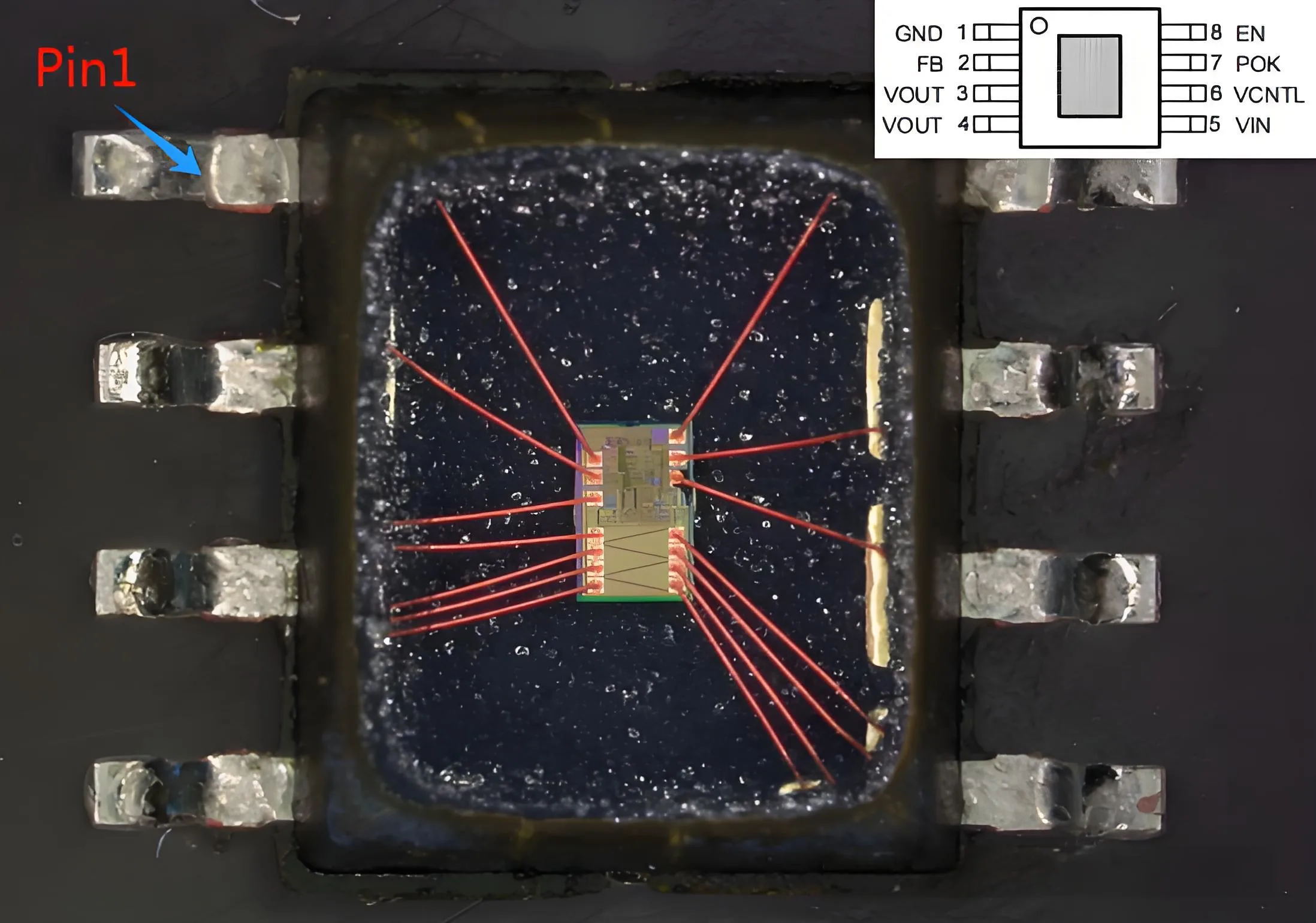
Der EOS des Chips wurde ausgebrannt
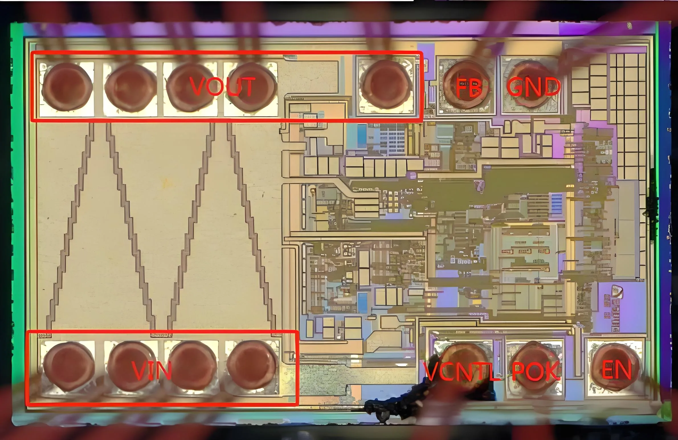
Der EOS des Chips wurde ausgebrannt
3) Ursachenanalyse: Es wird vermutet, dass eine durch VCNTL eingeführte Überspannungsspannung den Chipfehler verursacht hat. Der VCNTL -Pin wird als Eingangsstift definiert, Dies könnte möglicherweise überspannten Stress auftreten.
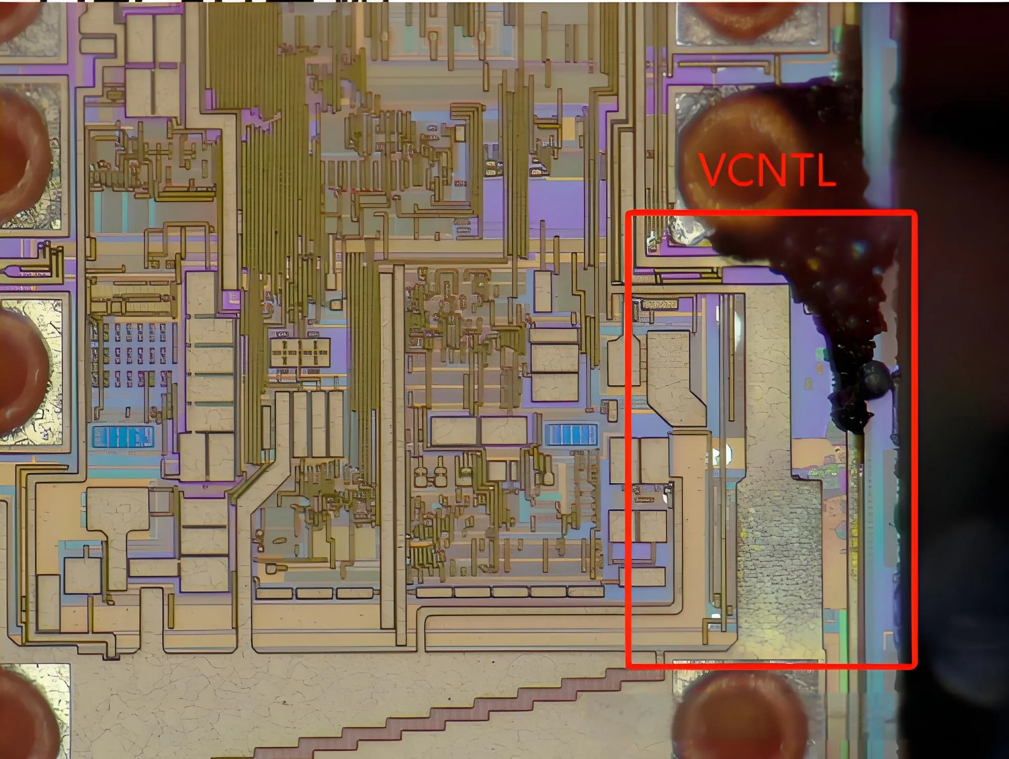
VCNTL führt übermäßige elektrische Spannung ein, die zum Versagen führt
Eine weitere Analyse ergab, dass die Metallmorphologie entlang des VCNTL-Vin-Links geschmolzen erschien, und die Messung der IV zwischen VCNTL und VIN zeigten einen Kurzschluss. daher, Der Chip scheiterte aufgrund der von VCNTL eingeführten Überspannungsspannung. Die Analyse des Logikblockendiagramms des Chips stimmte mit seiner logischen Funktion mit dem Ausfallphänomen überein.
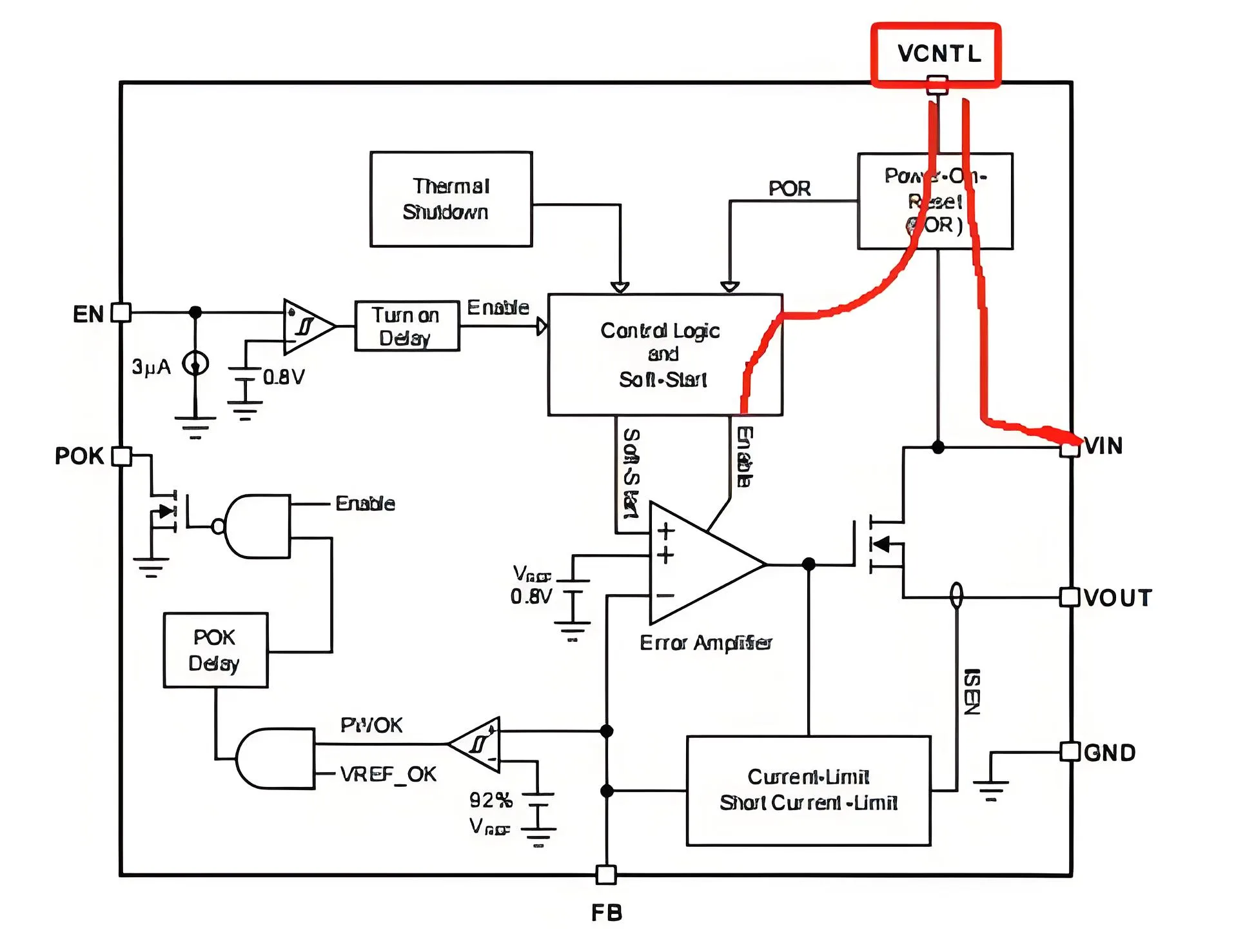
Chip -Logikdiagramm
Das Entfernen der oberen Metallschicht hat klargestellt, dass der Versagen des Chips tatsächlich durch über Voltsspannung durch VCNTL verursacht wurde.
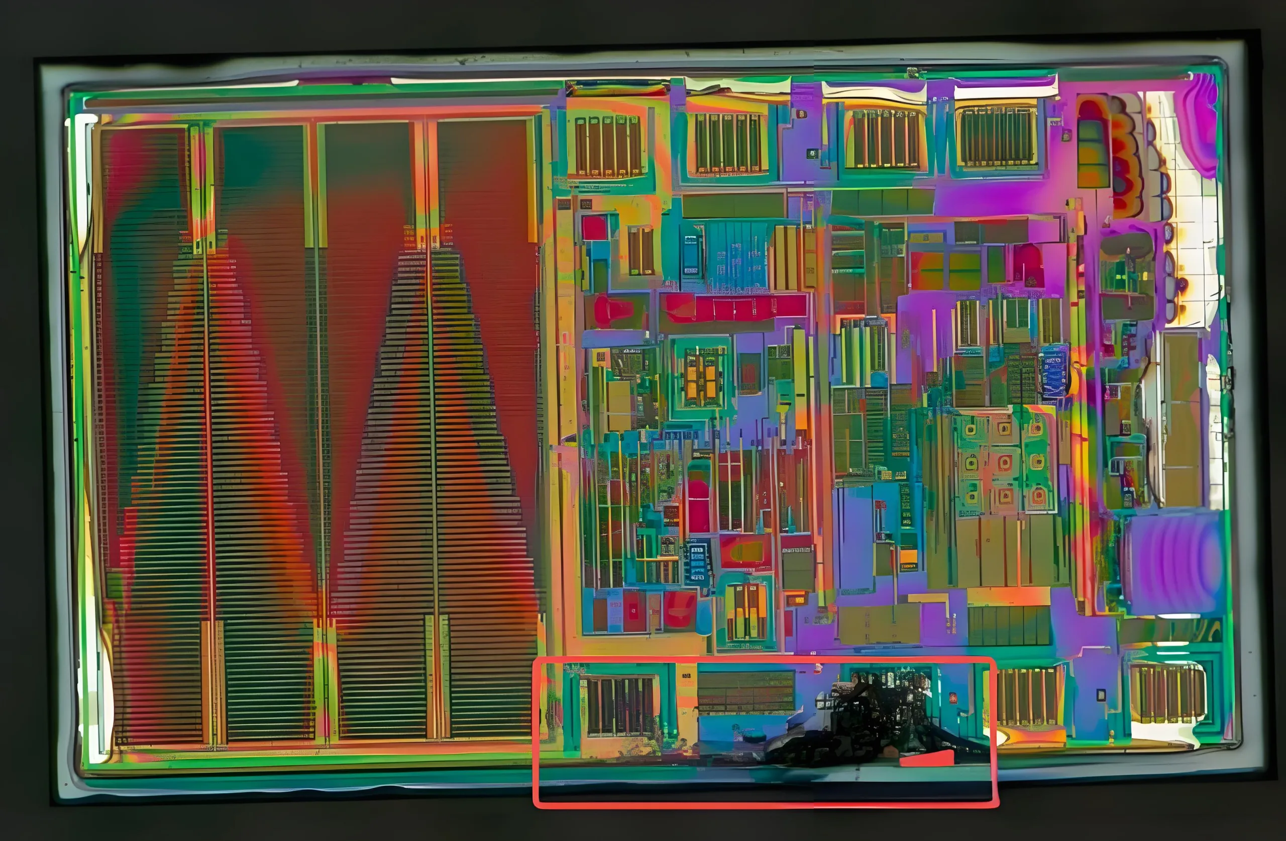
VCNTL führt übermäßige elektrische Spannung ein, die zum Versagen führt.
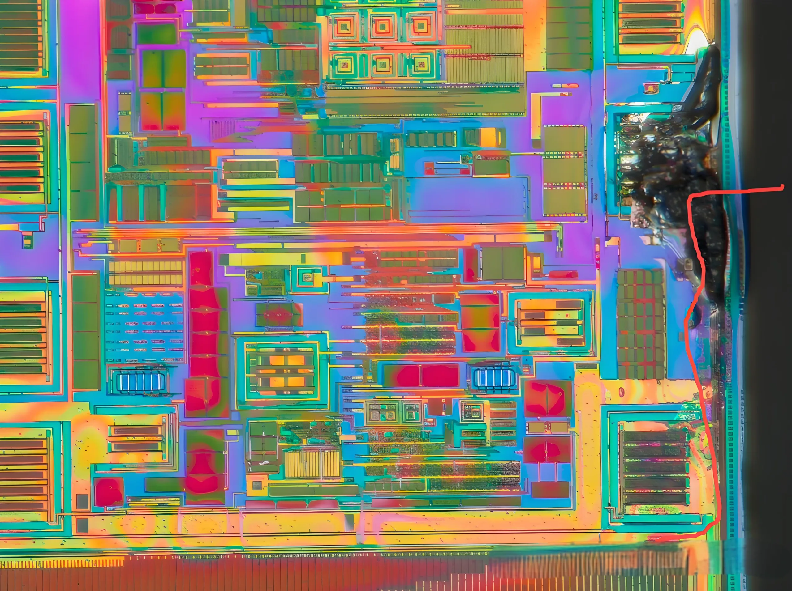
VCNTL führt übermäßige elektrische Spannung ein, die zum Versagen führt.
4) Bestätigung der Boardebene: Nach Analyse, Es wurde bestätigt, dass die Beschädigung anderer peripherer Geräte auf der Tafel dazu führte. Somit, Dieser Chip war ein “Opfer.”
EOS ist das häufigste Phänomen, das bei der Versagenanalyse auftritt. Die Ermittlung der Grundursache durch EOS -Versagensymptome ist eine Herausforderung und verpflichtet Analysten, ein klares logisches Denken und umfassende Kenntnisse zu haben.
 UGPCB-LOGO

