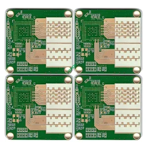
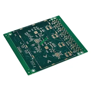
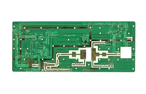
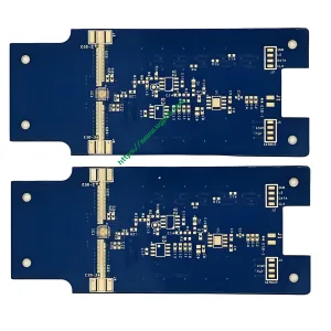
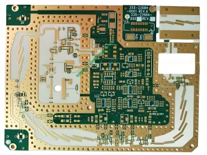
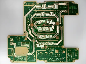
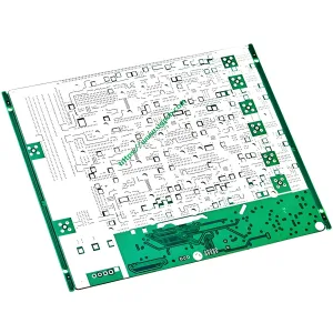
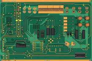
Radar -PCB ist ein PCB -Substrat, das im Radar verwendet wird, häufig in Kommunikationsradar -PCB verwendet, Erkennungsradarplatine, Millimeter-Wellen-Radar, usw. Derzeit, Das in ADAS verwendete Millimeter-Wellen-Radar entwickelt sich sehr schnell. Für das Millimeter-Wellenradar von ADAS, Bitte klicken Sie auf Millimeter-Wellenradar.
Radarplatine benötigt Hochfrequenz-PCB-Materialien. DK und DF dieser Art von Hochfrequenz-PCB-Materialien benötigen eine spezielle Fertigungskontrolle, UGPCB Company verwendet DK 2-16 Hochfrequenz-PCB-Materialien zur Herstellung von Radar-Leiterplätzen, wie Teflon -PCB -Materialien, Keramik -PCB -Materialien, und Kohlenwasserstoff -Leitermaterialien.
Radar strahlt elektromagnetische Wellen aus. Funkwellen werden durch die Antenne des Radars emittiert und reflektiert von Hindernissen vorne. Radar ist ein magisches elektrisches Gerät, das den Abstand zwischen Objekten misst.
Ein primäres Radarsystem besteht aus einem Sender, der elektromagnetische Wellen erzeugt, Eine Antenne, die elektromagnetische Wellen leitet, Ein Empfänger, der das Rückgabebericht verstärkt, und ein Display, das den Standort des Ziels ausdrückt. Das Radar gibt einen winzigen Teil der elektromagnetischen Welle aus, die am Ziel bestrahlt werden, Streuung in alle Richtungen.
Das Radar empfängt das Rückstreutensignal über die Antenne. Dann überträgt das Radar diesen Teil der Energie an den Empfänger, identifiziert die Existenz des Ziels gemäß den Symbolen im Empfänger, und misst seine Position und Geschwindigkeit. Das Radar schätzt den Abstand des Ziels gemäß der Zeit, die für die übertragene elektromagnetische Welle erforderlich ist, um den Reflektor zu erreichen und zur Empfangsantenne zurückzukehren. Die Richtung der Antenne bestimmt die Winkelposition des Zielobjekts. Radar wurde im Militär weit verbreitet, Luftfahrt, Navigation, Meteorologie, und andere Abteilungen, weil es die räumliche Position des Ziels schnell und genau bestimmen kann.
Radar ist in militärische und zivile Typen unterteilt.
1. Air Intelligence Radar. Verwendet zur Suche, Monitor, und Luftziele identifizieren. Es enthält Luftwartradar, Anleitung Radar, und zielgerichtete Radar, sowie Radar mit geringer Höhe, die zum Nachweis von Zielen mit geringer Höhe und Ultra-niedriger Höhe entwickelt wurde.
2. Marine Warnradar. Radar zum Nachweis von Oberflächenzielen wird normalerweise auf verschiedenen Oberflächengefäßen oder Küsten und Inseln montiert.
Klassifizierung von Radaren
Nach Funktion klassifizieren: Warnradar, Anleitung Radar, Artillerie -Zielradar, Luftkontrollradar in der Luft, Höhenmessung des Radars, Blind Landing Radar, Geländevermeidungsradar, Terrain -Tracking -Radar, Bildgebungsradar, meteorologisches Radar, usw.
Klassifiziert durch Arbeitssystem: konisches Scan -Radar, Monpulseradar, Passives Phasen -Array -Radar, aktives Phasen -Array -Radar, Impulskompressionradar, Frequenz-Agile-Radar, MTI Radar, Mtd Radar, PDRADAR, Synthetic Aperture Radar, Rauschradar, Schockradar, Bistatische/multi-statische Radar, Himmels-/Erdwellen-Über-Range-Radar, usw.
Klassifizieren Sie durch Arbeitswellenlänge: Meterwellenradar, Dezimeterwellenradar, Zentimeterwellenradar, Millimeter-Wellen-Radar, Lidar/Infrarotradar.
Es wird gemäß den Koordinatenparametern des Messziels klassifiziert: Zwei-Koordinate-Radar, Drei-Koordinaten-Radar, Geschwindigkeitsradar, Höhenradar, Anleitung Radar, usw.
Radarplatine
Das Antennenarray von Phased -Array -Radar besteht auch aus vielen Strahlungseinheiten und empfangenden Einheiten (angerufene Array -Einheiten). Die Anzahl der Einheiten hängt mit der Funktion des Radars zusammen, die zwischen Hundert bis Zehntausenden reichen können. Diese Elemente sind regelmäßig in der Ebene angeordnet, um eine Array -Antenne zu bilden. Unter Verwendung des Prinzips der elektromagnetischen Wellenkohärenz und der Steuerung der Phase des Stroms, die jeder Strahlungseinheit mit dem Computer gespeist werden, Die Richtung des Strahls kann zum Scannen geändert werden, Es wird also als elektrisches Scannen bezeichnet. Die Strahlungseinheit sendet das empfangene Echo -Signal an den Host, um die Radarsuche abzuschließen, Verfolgung, und Messung des Ziels. Zusätzlich zum Antennenoszillator, Jede Antenneneinheit verfügt auch über notwendige Geräte wie einen Phasenschieber. Verschiedene Oszillatoren können durch Phasenschieber in verschiedene Phasenströme eingespeist werden, um Strahlen mit unterschiedlicher Richtfähigkeit im Raum zu strahlen. Desto mehr Elemente der Antenne, Die möglichen Ausrichtungen des Strahls im Raum. Die Arbeitsbasis dieses Radars ist die Phasensteuerbare Array -Antenne, das heißt “Phased Array”.
Phased Array -Radar kann in zwei Arten unterteilt werden. Erste, Passives Radar, Pesa kurz, ist eine Art Radar mit relativ geringer technischer Leistung. Es hat sich in den 1980er Jahren reif entwickelt und wird auf Schiffe und kleine und mittelgroße Flugzeuge angewendet. Die zweite ist die Radartechnologie mit besserer Leistung, Gute Entwicklungsaussichten, und höhere technische Leistung als die erste. Diese Technologie wurde erst Ende der neunziger Jahre angewendet und begann auf Kämpfer- und Schiffsborne -Systeme angewendet zu werden. Diese Technologie ist “aktiv (Aesa)”.
Phased Array Radar verwendet im modernen Krieg die elektronische Positionierungstechnologie weit verbreitet, und hat eingehende Erkundungen durchgeführt. Im Militär, Es ist eine große Nachfrage nach Angriffen mit großer Reichweite im Meer und in der Luft, Dies erfordert die tiefere Anwendung der Positionierungstechnologie.
Bereichsmessung: Die Reichweite ist alltäglich zum Testen und Identifizieren von Waffen und Ausrüstung, und kann auch Raumschiffe testen und starten. Die Messung des Schießbereichs basiert auf dem Test und dient der Anwendung.
1. Raketenbereich. Der Raketenbereich ist in zwei Teile unterteilt, nämlich, der obere Bereich und der untere Bereich. Der Oberbereich wird auch als Startbereich oder Kopfbereich bezeichnet, und die untere Reichweite wird auch als Wiedereintrittsbereich oder den Landeplatz und den Landeplatz bezeichnet. Die obere Schießstand der Rakete ist der Ort, an dem die Rakete gestartet wird. Seine Hauptaufgabe ist es, zu überwachen, ob die Flugumlaufbahn der Rakete die voreingestellte Umlaufbahn ist, Dies ist die Grundlage für die Bestätigung der Sicherheit des Schießbereichs, und Daten für verschiedene physikalische Phänomene der neuen Rakete im Flugprozess bereitzustellen. Der untere Bereich der Raketen ist hauptsächlich ein Ort, um die Eigenschaften von Raketenzielen und Anti-Missile-Waffensystemen zu messen und zu identifizieren.
2. Space Shooting Range. Strategische Raketen sind die Grundlage für Raumstartfahrzeuge. daher, Die frühe Raketen -Shooting -Reichweite ist immer noch ein stolzer Startpunkt des Raumfahrzeugs.
3. Herkömmliche Schießstand. Die herkömmliche Schießerei kann in eine herkömmliche Waffenserieserie und die elektronische Schießklasse unterteilt werden. Darunter, Das konventionelle Waffenschreibbereich stand in verschiedenen Ländern immer im Mittelpunkt der kräftigen Entwicklung. Es hat die Eigenschaften von großer Kraft, hohe präzision, Mehrere Funktionen, gute Effizienz, und niedrige Kosten.
Radar -PCB -Design
Radar-PCB kombiniert verschiedene digitale und gemischte Signaltechnologien, Das Layout von PCB und das PCB -Design werden also schwieriger, Besonders wenn RF und Mikrowelle für Unterkomponenten gemischt sind. Ob Sie mit uns zusammenarbeiten, mit anderen Radar -PCB -Lieferanten, Oder entwerfen Sie Ihre eigene Radar -Leiterplatte, Sie müssen einige Angelegenheiten berücksichtigen.
Der Bereich der Radarfrequenzen ist normalerweise sehr hoch, Entwürfe über 1 GHz werden jedoch normalerweise als PCB -Radar angesehen. Wenn Ihre PCB -Betriebsfrequenz 1 GHz überschreitet, Sie befinden sich im Bereich von PCB -Radar. Das PCB-Radar verwendet sehr hochfrequente Mikrowellensignale.
Warum ist es so schwierig, HF und Radar -Leiterplatten zu entwerfen?
Es gibt viele Probleme bei der Gestaltung von Radar -Leiterplatten, Dies kann ernsthafte Auswirkungen auf Qualität und Produktivität haben. Zum Beispiel, Beim Einbetten des HF -Schaltkreises eines Designers in die PCB anderer Designer, Sie verwenden oft unterschiedliche Designformate, Die Effizienz muss also stark reduziert werden. Zusätzlich, Designer sind oft gezwungen, Änderungen im Design vorzunehmen, um mit der Verwendung von HF -Schaltungen zusammenzuarbeiten. Weil die Simulation häufig in der HF -Schaltung durchgeführt wird, eher als im Kontext des gesamten Radarplatine, Der signifikante Einfluss der Radarschaltplatine auf die HF -Schaltung kann weggelassen werden, Und umgekehrt.
Mit dem zunehmenden Gehalt an Radar -Leiterplatten, PCB -Designer und Ingenieure erkennen, dass zur Verbesserung der Produktivität und zur Produktqualität, Es ist am besten für sie, HF -Designherausforderungen selbst in ihren eigenen Designwerkzeugen zu lösen. Bedauerlicherweise, Die meisten Desktop -Radar -PCB -Design -Tools helfen ihnen nicht, diese Aufgabe zu vereinfachen.
Zum Beispiel, Sobald die erforderliche elektrische Leistung nach der Modellierung der Radarplatine mit einem HF -Simulator erzielt wird, Der Simulator erzeugt die Kupferfolienform der Schaltung (normalerweise im DXF -Format) Um es in PCB -Design -Tools zu importieren. Dieser Prozess bringt Designer oft einige Probleme mit sich. Zum Beispiel, Sie können es nicht in Kupferfolienform umwandeln, da sie die DXF -Datei nicht richtig konvertieren können. In diesem Fall, Designer müssen DXF -Dateien manuell importieren, Dies kann zu menschlichen Fehlern und Fehlern in Form und Größe des HF -Schaltungsfehlers führen.
Die Herausforderungen, denen sich Radar -PCB -Designer oder Ingenieure beim Versuch, das Layout für HF- und Mikrowellenschaltungen zu entwerfen.
Warum müssen Sie den richtigen Radar -Platar -PCB -Hersteller auswählen??
Radarplatine reagiert sehr empfindlich gegenüber Rausch, Impedanz, elektromagnetisch. Hochwertige Radar-PCB-Hersteller konzentrieren sich auf die Beseitigung von Einflussfaktoren im Herstellungsprozess. Es wird nicht erwartet, Aus diesem Grund kann die Auswahl eines perfekten Radar -PCB -Herstellers Ihr Produkterlebnis ändern.
Warum wählen Sie UGPCB für die Radar -PCB -Herstellung??
UGPCB verfügt über mehr als zehn Jahre Erfahrung in der Radar -PCB -Herstellung, und UGPCB -Fachkräfte verfügen über professionelle Kenntnisse in der PCB -Fertigung basierend auf Radar -PCB -Materialien. UGPCB hat sich für verschiedene Produkte auf der ganzen Welt für die Bereitstellung von Radar -PCB -Fertigung verpflichtet. UGPCB bietet den Kunden zufriedenstellende Dienstleistungen und stellt langfristige kooperative Beziehungen zu Kunden auf.
 UGPCB-LOGO
