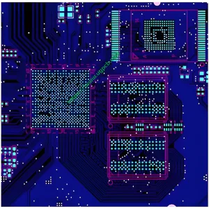
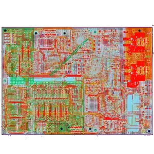
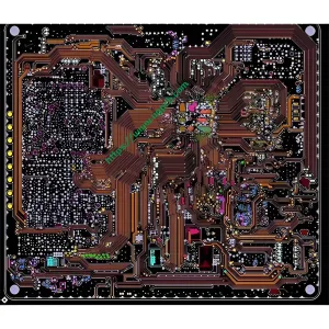
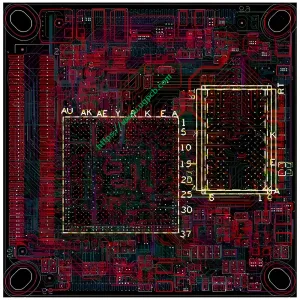
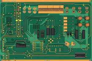
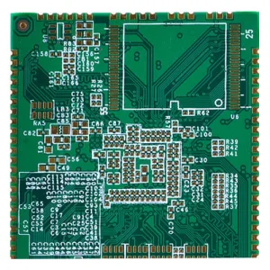
Versatilidad extraordinaria
Las tablas HDI son ideales cuando el peso, espacio, fiabilidad, y el rendimiento son las principales preocupaciones.
Diseño compacto
Combination of Blind, Buried, and Micro Vias
La combinación de ciegos, enterrado, y Micro Vias reduce los requisitos de espacio de la placa.
Mejor integridad de la señal
Via-in-Pad and Blind Via Technology
HDI utiliza a través de PAD y ciegos a través de la tecnología, which helps keep components close to each other, Reducir las longitudes de la ruta de la señal.
Removal of Through-hole Stubs
La tecnología HDI elimina los talones de agujeros, reducing signal reflections and improving signal quality.
Shorter Signal Paths
Due to shorter signal paths, HDI significantly improves signal integrity.
Alta fiabilidad
Stacked Vias
La implementación de VIA apilados hace de estos tableros una súper barrera contra las condiciones ambientales extremas.
Rentable
La funcionalidad de una placa de agujero de 8 capas estándar (PCB estándar) can be reduced to a 6-layer HDI board without compromising quality.
 UGPCB LOGO
