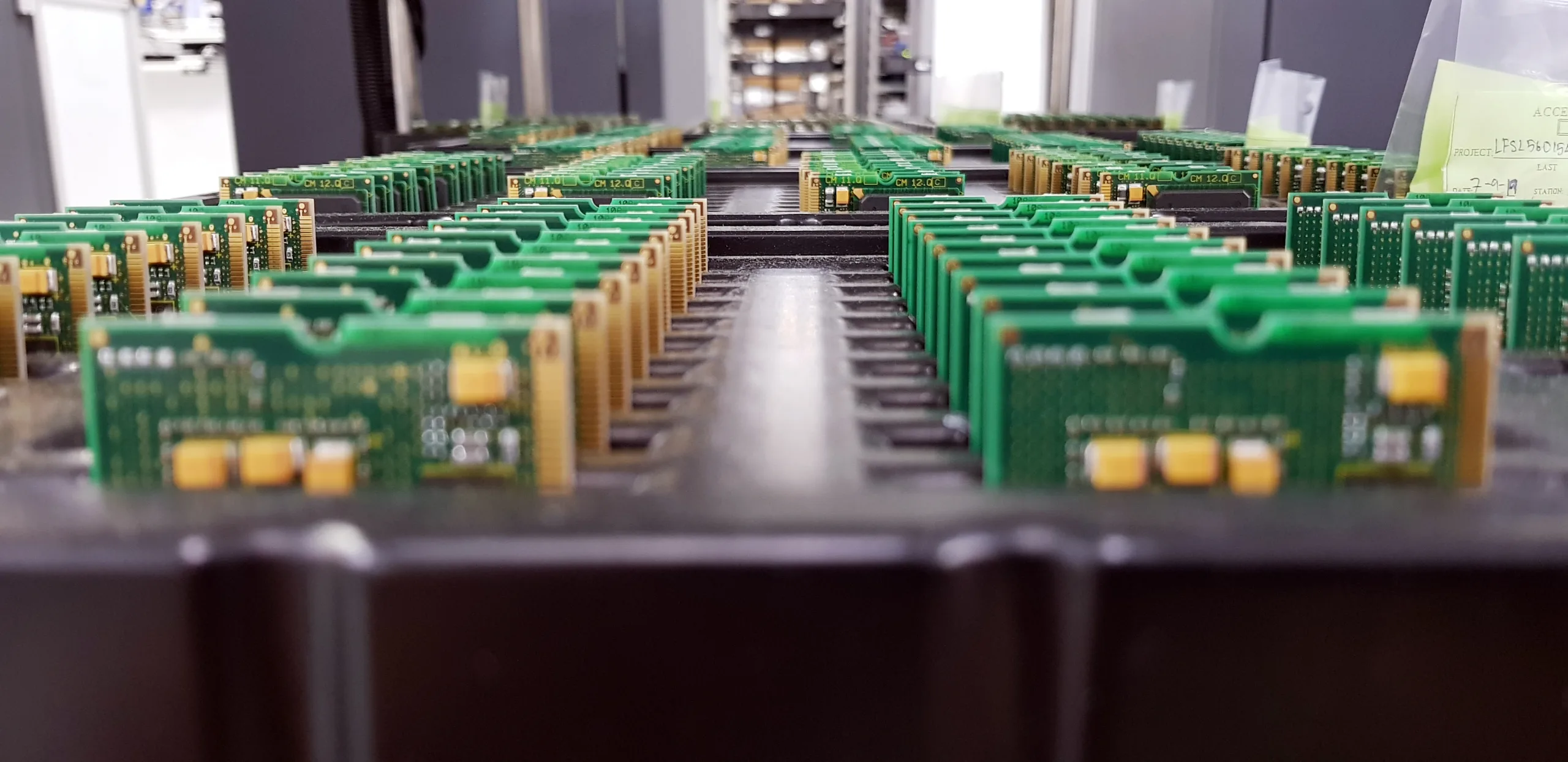
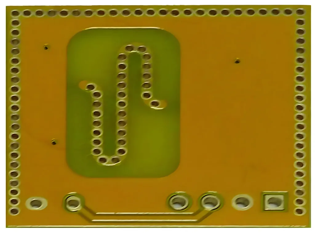
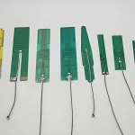
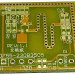
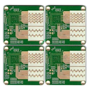
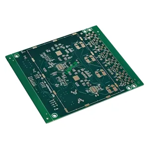
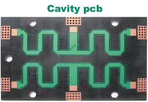
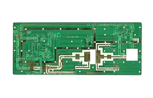
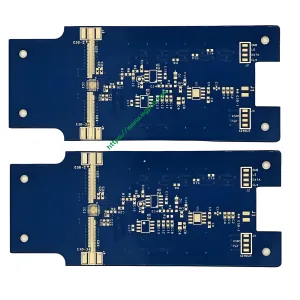
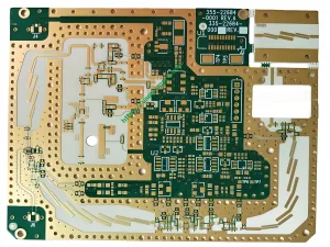
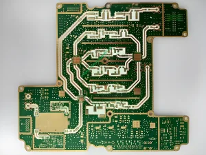
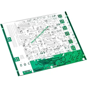
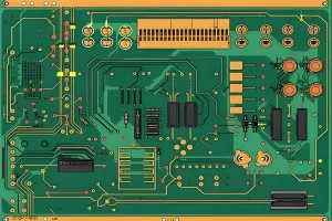
UGPCB provides antenna PCB, which is mainly used for GPS antenna PCB, wifi antenna PCB, NB-IoT antenna PCB, FPC antenna, and 5G antenna PCB.
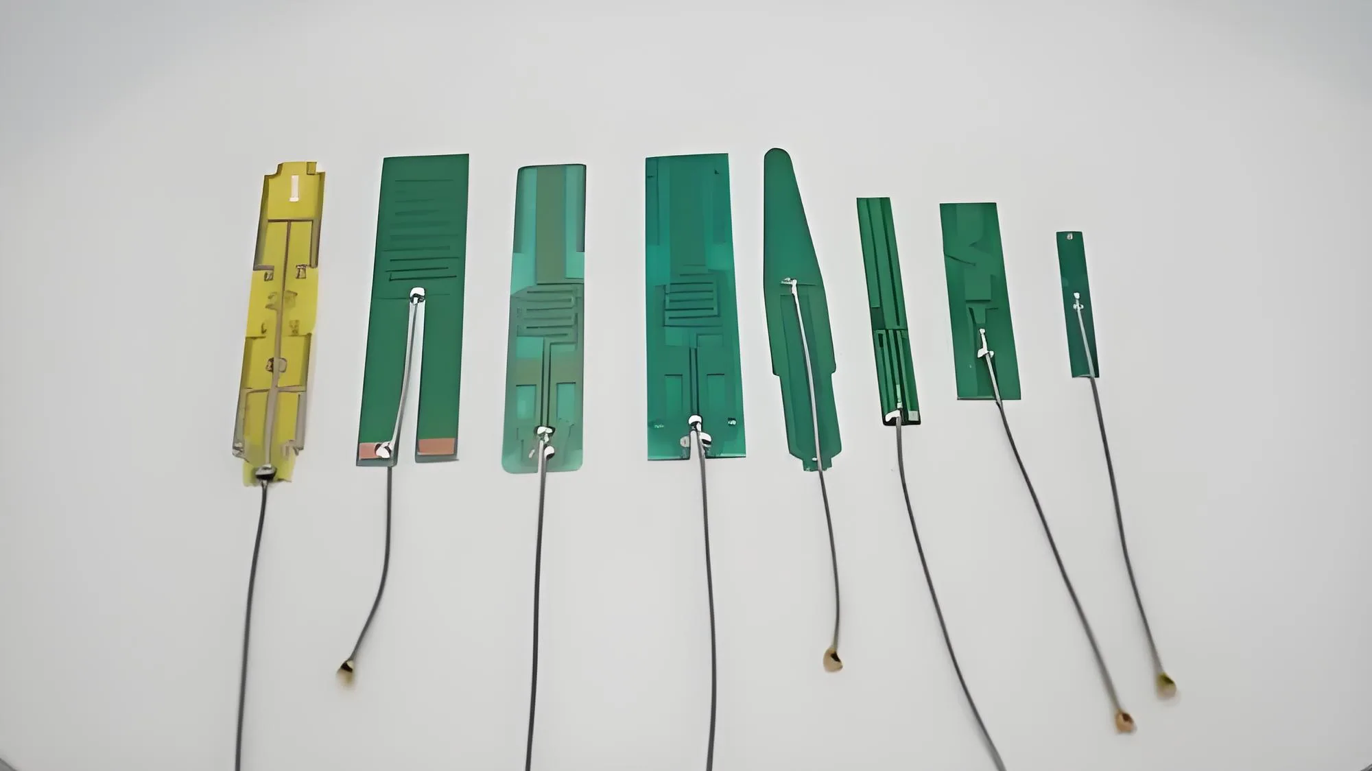
Carte PCB d'antenne haute fréquence
PCB antenna refers to the part of PCB used for wireless reception and transmission. The antenna is a transducer. During transmission, it converts the high-frequency current of the transmitter into spatial electromagnetic waves. When receiving, the antenna converts the electromagnetic wave intercepted from space into a high-frequency current that is fed into the receiver. Antenna PCB design is an important part of the design of small power, short distance wireless transceiver and receiver device for radio frequency identification system.
A good antenna system can optimize the communication distance. There are many kinds of antenna PCB, different applications need different antenna PCB. In a small power, short distance RFD system, an antenna system with reliable communication and low cost is needed. PCB ring antenna is a common one.
Antenna PCB receives and transmits signals from wireless devices and has been widely used in telecommunications. Avec l'avènement du réseau 5G, De plus en plus d'appareils électroniques ont besoin d'une communication de PCB d'antenne.
Antenna PCB materials should have high frequencies and FR-4 PCB materials usually do not have good performance. Here we list the materials available for antenna PCB manufacturing, PCB de Rogers, PCB en téflon, Arlon PCB, PCB taconique, Nelco PCB, FR-5 PCB, Dupont PCB, PCB isolé.
The length of the antenna is about a quarter of the wavelength of the electromagnetic wave, so the lower the signal frequency, the longer the antenna length. Donc, a long pole antenna is needed for FM radio around 100MHz, and an external long pole antenna is needed for intercom around 400MHz. The 433MHz wireless serial port commonly used in the Internet of Things also uses an external antenna.
Some antennas, such as one-eighth or one-sixteen wavelengths, can also be used, but the efficiency will decrease. Some devices use the “short antenna + LNA” méthode, and can also achieve the reception effect of a long antenna. Cependant, for a short antenna to transmit a long antenna, the transmission power needs to be increased. Donc, the intercom needs to transmit signals, which are all long external antennas, while FM radio only receives no radio and has a built-in receiving antenna. Par exemple, 2G (900MHz), 4G (700-2600MHz), WIFI and Bluetooth (2.4GHz), GPS (1.5GHz), which are commonly used methods of Internet of Things communication, can be used as built-in PCB antennas. For small-sized products such as handsets, wearable designs, smart homes, etc., external antennas are rarely used, and built-in PCB antennas are commonly used. High integration, beautiful product appearance, a slightly weaker performance than an external antenna.
Compared with external antennas, built-in antennas such as PCB antenna, FPC antenna, LDS antenna, and WiFi antenna have their own unique product form. These three are not different, each has its own advantages and applications.
Built-in PCB antenna
The built-in PCB antenna is a conductor that lays out directly on the PCB circuit board.
The built-in PCB antenna is widely used on single-band module circuit boards such as Bluetooth module, WIFI module, ZIGBEE module, etc..
Benefits of the built-in PCB antenna: Cost-free, no need to debug again once tuned.
The disadvantage of a built-in PCB antenna: only suitable for a single band, such as Bluetooth, wifi. The performance of PCB antennas in different batches will be different.
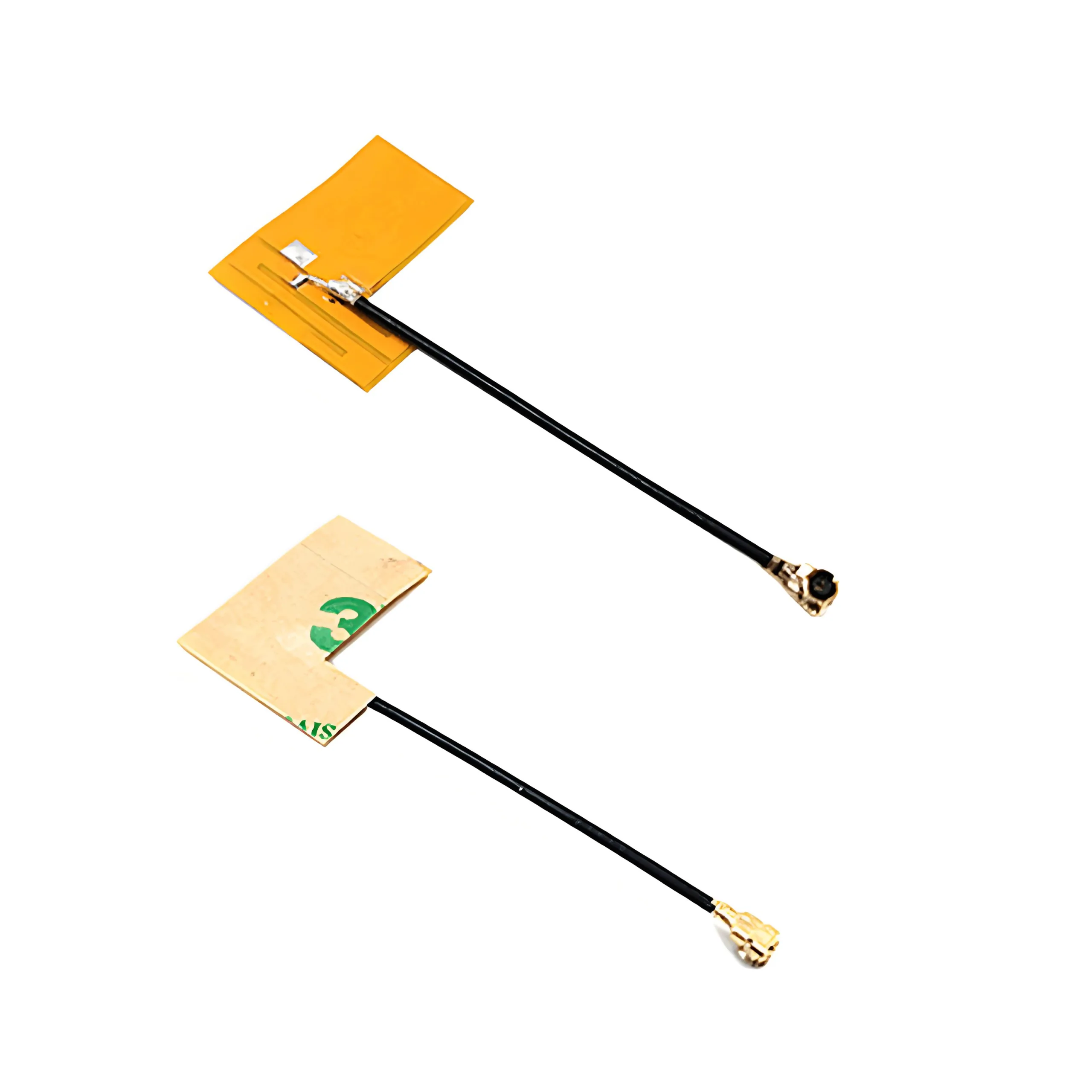
FPC antenna
FPC antenna
The FPC antenna is equivalent to pulling out the antenna line on the PCB board and using other external metals to make the antenna. Usually used in mid-low-end mobile phones and smart hardware products with complex bands.
Advantages of FPC antenna: It is suitable for almost all small electronic products, and can be used as a complex antenna with more than 10 bands. It has good performance and low cost.
Disadvantages of FPC antenna: need to be debugged separately for each product.
WiFi antenna
WiFi antenna refers to the communication antenna with a working frequency ranging from 2.4GHz to 2.5GHz, which is mainly used for WLAN, Bluetooth, etc.. According to the actual use requirements, the samples of wifi antenna can be divided into sucker antenna, external rubber antenna, FRP antenna, built-in PCB antenna board, built-in FPC antenna, etc.. Wifi antenna PCB has strict requirements for PCB manufacturer.
Key Points for Manufacturing Antenna PCB
1. Antenne PCB, if cost and size are not considered, can choose other antennas, such as patch antenna (petite taille, medium performance, medium cost) or external whip antenna (large size, haute performance, high cost). PCB antenna is the cheapest, medium size, as long as it is properly designed and can achieve sufficient performance.
2. The dielectric constant (Ne sait pas) of circuit laminates is the first factor many PCB antenna engineers should consider when designing microstrip antennas. The influence of the Dk value of the printed circuit board material on the circuit size. For a given frequency microstrip patch antenna, the patch size decreases with the increase of the Dk value.
3. For PCB antennas, thicker PCB circuit board materials are easier to radiate energy outward. En général, to design antenna radiation units such as microstrip patches, you should choose circuit board materials that are relatively thick and have lower Dk values, tel que 2.2 à 3.5. Despite the low radiation efficiency of PCB materials with higher Dk values, it is more challenging to design PCB antennas using PCB materials with higher Dk values. Cependant, when smaller patch antennas are needed, higher Dk value circuit board materials can still be used by optimum design.
4. Compared to the ceramic or PTFE media of the PCB laminate, the surface roughness of the copper foil of the laminate has an effect on the antenna. En même temps, for circuits with the same dielectric material (Par exemple, PTFE with glass or ceramic fillers), the effect of rough copper foil surface on the antenna is greater than that of the smooth copper foil surface.
5. PCB antenna and other passive devices made of PCB material can also affect the performance of PCB antenna after surface electroplating. Ferromagnetic materials, such as nickel, can seriously affect the performance of PCB antennas. The tin process usually has better performance than the bare copper circuit, while electro-routing using chemical nickel-gold (ACCEPTER) with nickel produces poor performance.
6. Circuit surface cleanliness is beneficial to reduce the performance of microstrip PCB antennas and other microstrip passive devices. Soldered circuit boards usually have better performance than bare copper circuits. Clean circuit boards without residual wet chemical treatment are the important basis for improving the performance of antenna PCB. The presence of any form of ionic contaminant or residue in the circuit may result in poor antenna performance.
7. The etching quality of the PCB circuit board is also very important for the performance of antenna PCB. If the copper foil conductor is not sufficiently corroded to cause rough and burr on the edge of the circuit, this may also degrade the performance of the PCB antenna.
As a carrier of high-speed signal transmission, microwave PCB antenna plays an increasingly important role in wireless communication and other fields with the trend of high-frequency evolution in the communication industry. UGPCB has a stable manufacturing process for microwave antenna PCB circuit boards. If you need antenna PCB manufacturing, veuillez contacter l'UGPCB.
 LOGO UGPCB
