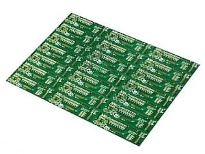
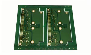
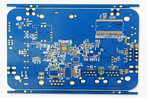
PCB inductance coil
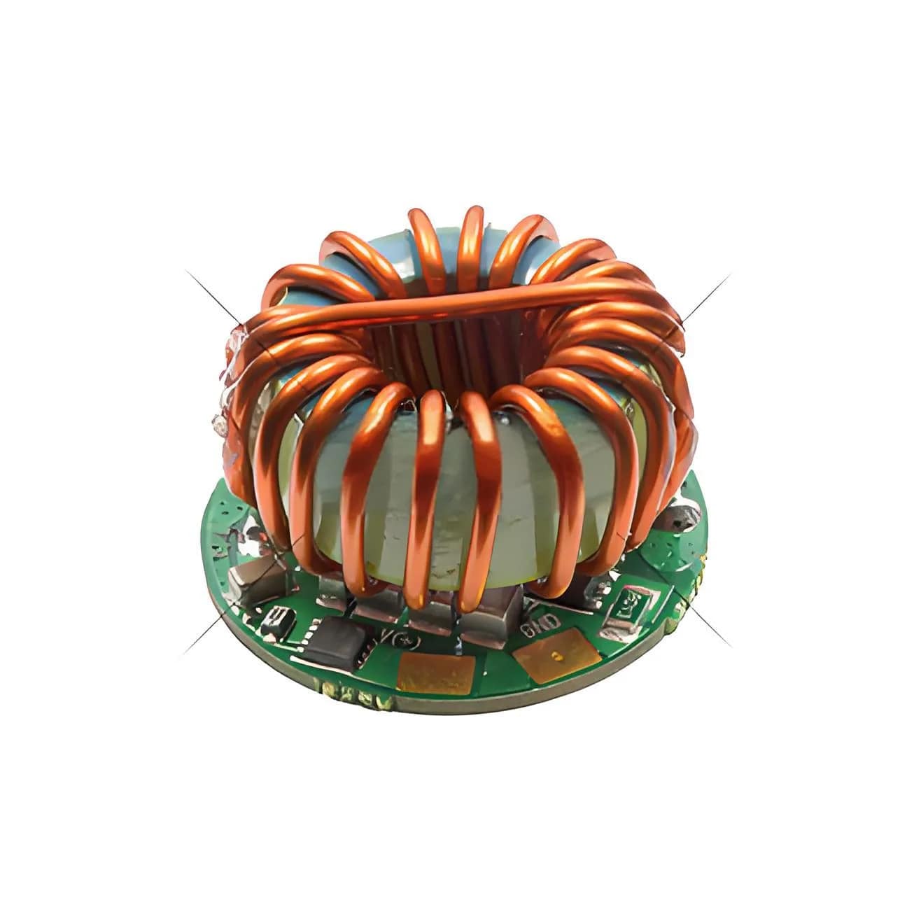
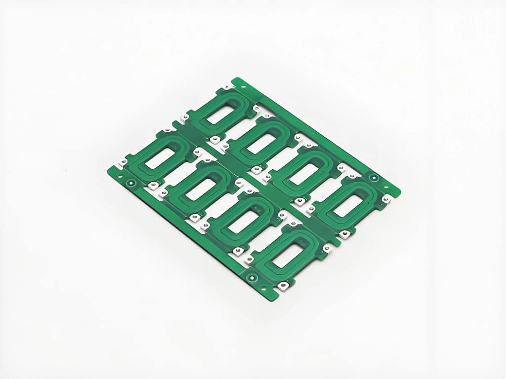
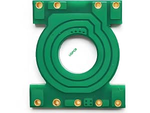
Thick copper magnetic coil PCB
We know that electricity generates magnetism and magnetism generates electricity. Both complement each other and always appear together. When a constant current flows through a wire, a constant magnetic field is always excited around the wire. When we bend this wire into an inductive coil, using the law of electromagnetic induction we have learned, we can determine that there is a magnetic field in the inductance coil. Prossimo, we put the inductance coil in a current loop. When the DC current in the circuit changes (such as from small to large or vice versa), the magnetic field in the inductor should also change. The changed magnetic field will bring about a new current. According to the law of electromagnetic induction, IL “new current” must be opposite to the original direct current, so that in a short time It has a certain resistance to the change of direct current. Tuttavia, once the change is completed, the current stabilizes and the magnetic field does not change any more, and there is no more obstruction.
When the traditional PCB needs to produce the function of magnetic flux / inductance, it is generally to design the wiring, pad and welding element jack on the PCB, and then weld the coil components. Even if the magnetic flux / inductance is small, the volume of the components is relatively large, and the welding area and space of the circuit board are large, which is not conducive to the miniaturization / miniaturization of the product. Inoltre, because the components are higher than the circuit board, it is easy to impact and change Shape and damage.
Magnetic coil PCB
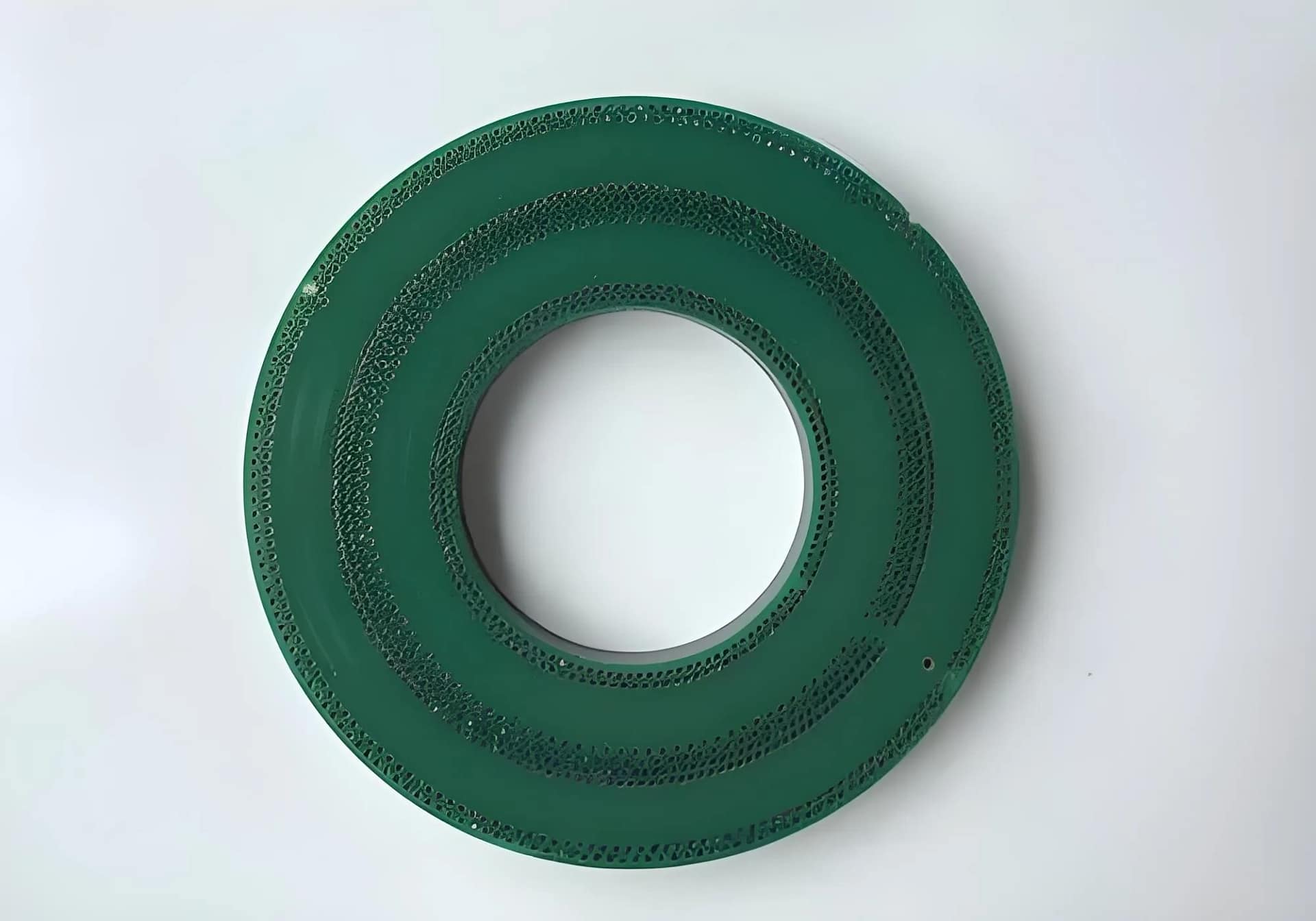
Thick copper magnetic coil PCB
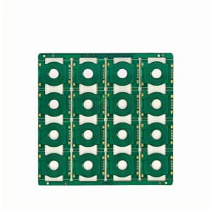
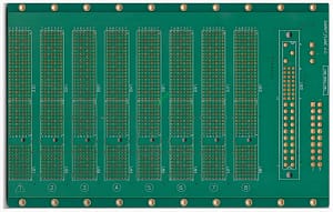
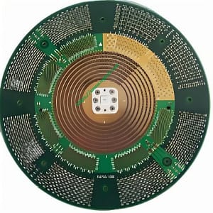
PCB circuit board with winding as the main circuit figure and etching circuit instead of traditional copper wire turns. It is mainly used in inductance components, and has a series of advantages such as high precision, good linearity and simple structure.
 LOGO UGPCB
