1. Automotive Instrument PCB 概要
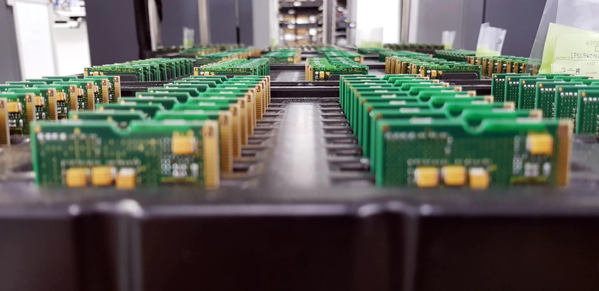
Our Automotive Instrument PCB is a high-performance プリント基板 engineered specifically for the rigorous demands of vehicle dashboard systems, including instrument clusters and display units. Designed with reliability and precision at its core, これ プリント基板 ensures stable operation of critical gauges, warning lights, and digital readouts that drivers depend on every day. で UGPCB, we specialize in manufacturing PCBs that meet the stringent quality and durability standards of the automotive industry, making us your trusted partner for automotive PCB and プリント基板 ソリューション.
2. What is an Automotive Instrument PCB?
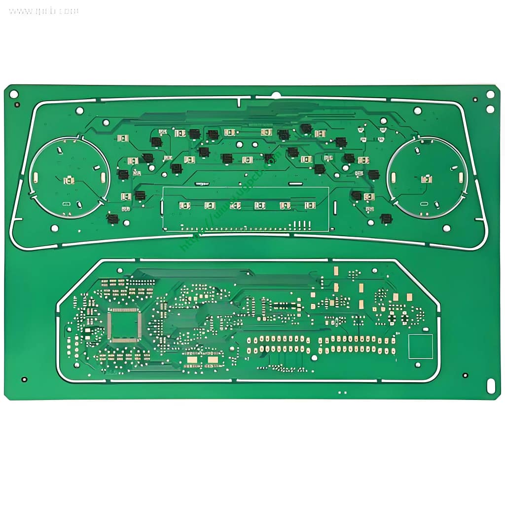
An Automotive Instrument PCB is the central nervous system of a vehicle’s instrument panel. It is a specialized printed circuit board that interconnects and provides a stable platform for electronic components like microcontrollers, センサー, LED indicators, and display drivers. This PCB is responsible for processing data from various vehicle sensors and accurately presenting information such as speed, engine RPM, fuel level, and engine temperature to the driver. The reliability of this PCB is paramount for vehicle safety and functionality, underscoring the importance of high-quality プリント基板の製造 そして PCBA組立サービス.
3. Design Key Points
The design of this PCB prioritizes signal integrity, 熱管理, 過酷な環境における長期信頼性.
-
材料の選択: The use of S1000-2 TG170 FR4 material provides a high glass transition temperature (TG), essential for withstanding the elevated temperatures found in automotive cabins.
-
トレースとスペース: With a minimum trace width and spacing of 6mil (0.15mm), the design supports a dense layout of circuits, allowing for a compact and feature-rich instrument panel.
-
銅の厚さ: A standard 1oz copper thickness ensures good current-carrying capacity and manufacturability.
-
表面仕上げ: The Organic Solderability Preservative (OSP) surface treatment offers a flat, planar surface ideal for fine-pitch components and provides excellent solderability for the PCBAアセンブリ プロセス.
4. それがどのように機能するか
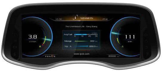
The Automotive Instrument PCB functions as an information hub. Electrical signals from vehicle sensors (例えば。, vehicle speed sensor, coolant temperature sensor) are transmitted to the PCB. Integrated circuits on the board, such as a microcontroller, process these signals. The PCB then routes the processed data to the appropriate output devices—stepper motors for analog gauges, LED drivers for warning lights, or digital interfaces for LCD/LED screens—resulting in the real-time display of vehicle metrics to the driver.
5. Primary Applications and Uses
This PCB is specifically designed for 自動車エレクトロニクス, with its primary use in:
-
Instrument Clusters (Analog and Digital)
-
Central Information Displays
-
Warning and Indicator Light Panels
-
Heads-Up Display (HUD) Control Units
-
Telematics Control Units
6. 分類
Printed circuit boards can be classified in several ways. This specific product falls into the following categories:
-
レイヤーカウントごとに: A 2-layer PCB, offering a robust and cost-effective solution for many automotive instrument applications.
-
By Material Type: A High-Tg FR4 PCB, indicating its enhanced thermal reliability.
-
アプリケーションによって: A dedicated 自動車PCB, designed to meet industry-specific standards like IPC-6012 and AEC-Q100 for components.
7. Materials Used
The core material is critical to the PCB’s performance.
-
基本材料: S1000-2 TG170 FR4. This denotes a halogen-free laminate with a Glass Transition Temperature (TG) of 170°C. The high Tg value ensures the board’s mechanical stability is maintained under high thermal stress, preventing delamination or warping, which is crucial for the long-term reliability of automotive PCBA 製品.
8. Key Performance Attributes
This PCB is built to deliver consistent performance:
-
High Thermal Endurance: The TG170 material ensures stable performance in high-temperature environments.
-
優れた信号の完全性: Precise control over trace width and spacing minimizes signal loss and crosstalk.
-
Long-Term Reliability: The OSP finish and high-quality base material provide robust resistance against environmental factors, ensuring a long operational lifespan.
-
機械的強度: A finished thickness of 1.2mm offers a rigid and durable structure that can withstand vibration and shock common in vehicles.
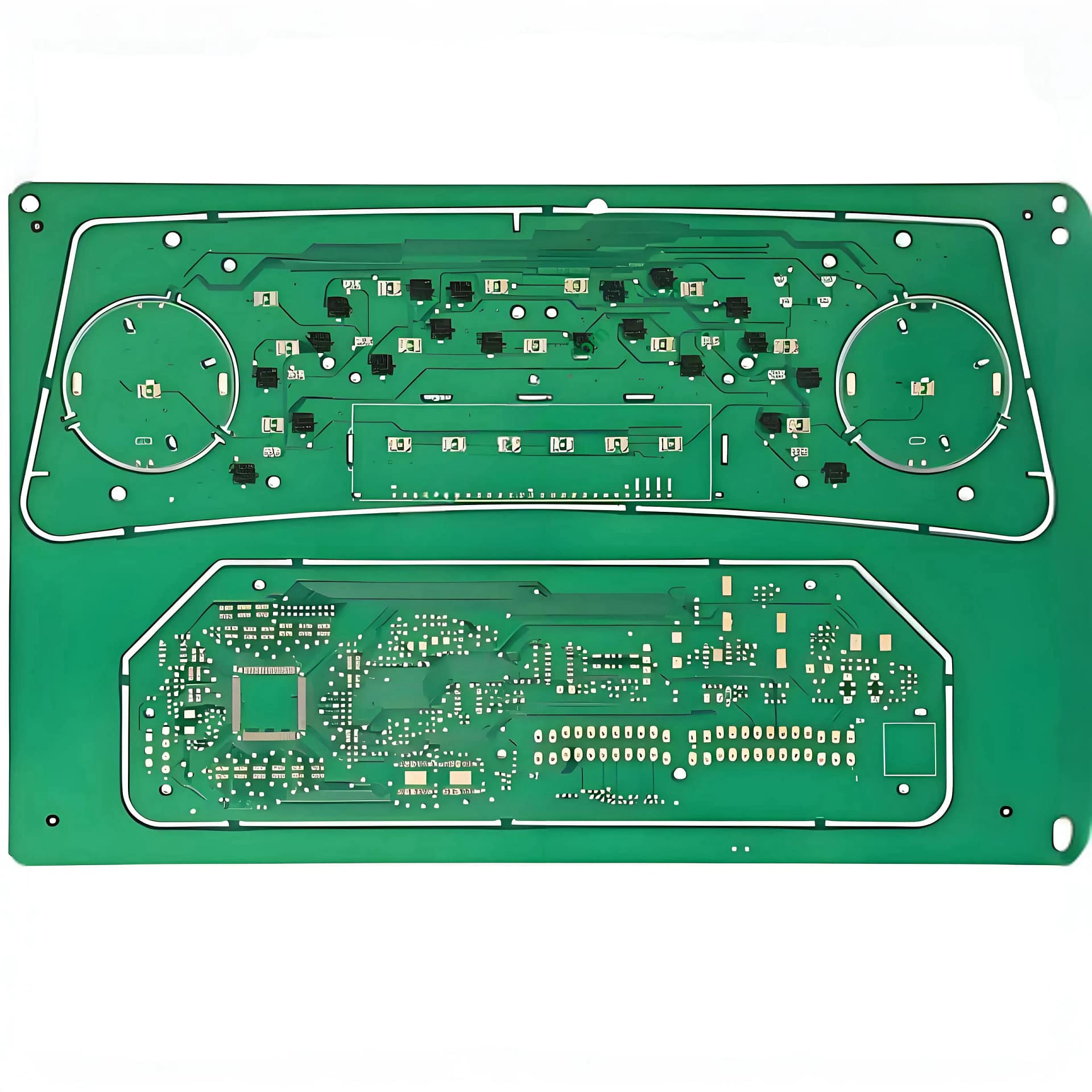
9. Physical Structure
The structure of this 2-layer Automotive Instrument PCB is defined by its key parameters:
-
レイヤー数: 2 レイヤー
-
仕上がり厚さ: 1.2mm
-
銅の厚さ: 1オンス (approximately 35µm) on each layer
-
はんだマスク色: Green or White (commonly used for high contrast and readability)
-
表面仕上げ: OSP (有機はんだ付け性防腐剤)
10. 特徴的な機能 & 利点
-
Automotive-Grade Reliability: Engineered with materials and processes that meet the high standards of the automotive industry.
-
Optimized for Assembly: The OSP surface and controlled impedance design facilitate a smooth and high-yield PCBAアセンブリ プロセス.
-
Thermal Robustness: The high Tg FR4 material prevents failure under thermal cycling, a common challenge in automotive PCB applications.
-
Compact Design Capability: Fine line technology (6MILトレース/スペース) allows for miniaturization of the instrument cluster.
11. 製造工程の概要
 Our production follows a stringent, IPC-compliant workflow to ensure quality:
-
材料の準備 & 掘削: The TG170 FR4 laminate is cut and drilled to create vias and mounting holes.
-
Patterning & エッチング: A photolithography process defines the circuit pattern, and unwanted copper is etched away to form precise traces.
-
ラミネート加工 & Curing: (For multi-layer boards; this 2-layer board undergoes a simpler process of solder mask application).
-
ソルダーマスクの塗布: The green or white solder mask is applied to protect the copper traces and define solderable areas.
-
表面仕上げ: The OSP coating is applied to protect the copper pads from oxidation and ensure solderability.
-
シルクスクリーン印刷: Component designators and logos are printed.
-
電気テスト & 最終検査: Each board undergoes automated optical inspection (あおい) and electrical testing to verify continuity and isolation, guaranteeing a defect-free automotive instrument PCB.
12. Typical Usage Scenarios
This PCB is ideally deployed in the heart of a vehicle’s dashboard. It is mounted directly behind the instrument cluster faceplate, interfacing with the following:
-
Stepper Motors that control the needles of analog speedometers and tachometers.
-
LED and LCD Displays that show odometer readings, trip computer data, and gear position.
-
Warning Light Bulbs or LEDs for indicators like check engine, oil pressure, and battery alerts.
-
Connector Sockets that link the cluster to the vehicle’s main wiring harness.


