
Redefining High-Density Interconnect Solutions for TWS Earphones
In today’s rapidly evolving consumer electronics landscape, the core design principles for True Wireless Stereo Bluetooth earphones remain consistent: 小型化, lightweight construction, そして multi-functionality. To achieve extended battery life, clearer call quality, and more compact internal layouts, traditional single-structure 硬い プリント基板 can no longer meet design requirements. UGPCB, leveraging extensive industry expertise, introduces our 6-layer Bluetooth headset rigid-flex PCB—specifically engineered to address these challenges. This board transcends conventional circuit boards; it serves as the foundation for unlocking breakthrough performance in your next-generation Bluetooth earphones.
製品の概要: Where Rigidity Meets Flexibility
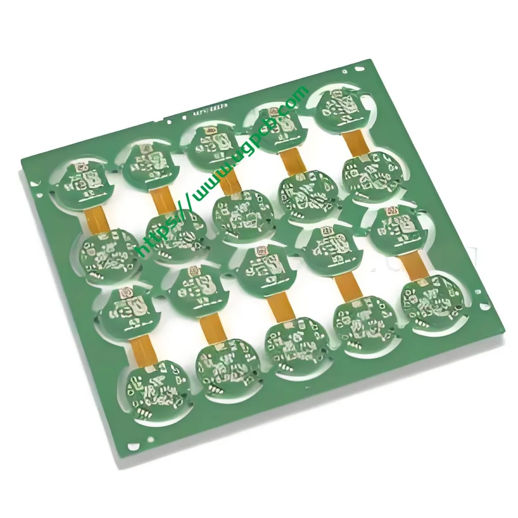
The UGPCB 6-layer Bluetooth headset rigid-flex PCB represents a sophisticated composite プリント基板 that seamlessly integrates 4 rigid layers with 2 flexible layers through precision lamination technology. This product is specifically engineered for high-density wiring requirements inside TWS Bluetooth earphones. With precise specifications and a dedicated model number, it delivers stable, reliable hardware support for premium Bluetooth audio devices.
Understanding Rigid-Flex PCB Technology
あ リジッドフレックスPCB combines the mechanical strength of rigid PCBs with the bendable characteristics of flexible FPC 回路. Traditional designs required connectors and cables to connect hard boards with flexible sections—consuming valuable space and introducing potential connection reliability issues. UGPCB’s rigid-flex boards integrate both elements into a unified structure, resulting in shorter signal paths and higher integration density.
コアパラメータと設計上の考慮事項
To accommodate the narrow, irregular cavities inside Bluetooth earphones, UGPCB has implemented precise parameter control:
-
モデル: 6レイヤーBluetoothヘッドセットPCB
-
Material Combination: FR-4 + PI. FR-4 provides stable component mounting platforms for rigid areas, その間 ポリイミド delivers exceptional flexural endurance for bendable sections.
-
層構造: リジッド4L / フレックス2L. This asymmetrical laminated configuration ensures ample multi-layer routing capability in motherboard areas while maintaining flexibility in connection zones.
-
仕上がり厚さ: 0.6mm. This ultra-thin profile perfectly matches Bluetooth earphone internal space constraints.
-
銅の厚さ: 1オズ. Balances current-carrying capacity with fine-line fabrication requirements.
-
表面処理: イマージョンゴールド. Provides excellent solderability and oxidation resistance.
-
最小トレース/スペース: 4ミル/4ミル. This falls within fine-line fabrication territory, demanding exceptional pattern transfer and etching control—critical for achieving 高密度相互接続.
Critical Design Guidelines:
When designing flexible areas, traces should feature curved transitions—avoiding right angles. At rigid-flex interfaces, avoid placing vias to prevent breakage during bending. UGPCB’s engineering team conducts rigorous design-for-manufacturability reviews using specialized software, ensuring every design detail meets production requirements before manufacturing begins.
Working Principle and Structural Analysis
これ 6-layer rigid-flex board operates based on its unique composite architecture:
-
Rigid Zones: Accommodate primary Bluetooth audio chips, power management ICs, and passive components. The 4-layer stack-up provides dedicated power and ground planes, effectively reducing electromagnetic interference and ensuring pure audio signal transmission.
-
Flexible Zones: Function as “bridges” between rigid sections. The 2-layer FPC can bend freely, connecting main boards with microphones, batteries, or antenna modules—eliminating cables and connectors entirely.
-
Metallized Interconnects: Through copper deposition and electroplating, conductive layers form on hole walls at rigid-flex boundaries, establishing electrical connections between rigid and flexible circuit layers.
分類と資料: Why FR-4 + PI?
分類: Based on process and structure, this product qualifies as a multi-layer rigid-flex board, specifically categorized as a rigid-flex composite board.
材料特性:
-
-
-
-
FR-4 (Rigid Layer) : As the industry-standard epoxy glass fabric substrate, FR-4 delivers exceptional mechanical strength, 耐熱性, and dimensional stability—ensuring reliable large-component soldering.
-
-
-
-
PI (Flexible Layer) : ポリイミド film represents the premier flexible base material, offering outstanding temperature resistance (compatible with lead-free soldering) and minimal dielectric loss, withstanding tens of thousands of dynamic bending cycles.
-
表面仕上げ: イマージョンゴールド: Electroless nickel immersion gold provides excellent solder joint flatness and wettability, while the gold surface prevents oxidation, extending earphone service life.
製造工程: Precision Engineering Delivers Quality
UGPCB 6-layer rigid-flex board undergoes sophisticated manufacturing sequences:
-
Inner Layer Circuitry: Fabricate 4 rigid inner layers and 2 flexible inner layers separately. あおい optical inspection verifies that 4ミル/4ミル fine-line patterns remain free from shorts or opens.
-
ラミネート加工: 使用する No-Flow Prepreg, precisely align rigid and flexible sections before single-step lamination under high temperature and pressure. This critical process demands precise resin flow control to prevent bleed-out from entering flexible zones and compromising bendability.
-
Drilling and Copper Deposition: Combine mechanical drilling with laser drilling to create micro vias. Copper deposition establishes interlayer connectivity.
-
表面仕上げ: Apply 浸漬ゴールド with uniform thickness and bright white appearance.
-
Profiling and Coverlay Opening: Use laser or controlled-depth routing to precisely open flexible area coverlays, releasing flexible sections for unimpeded bending.
アプリケーション: Powering the Core of TWS Earphones
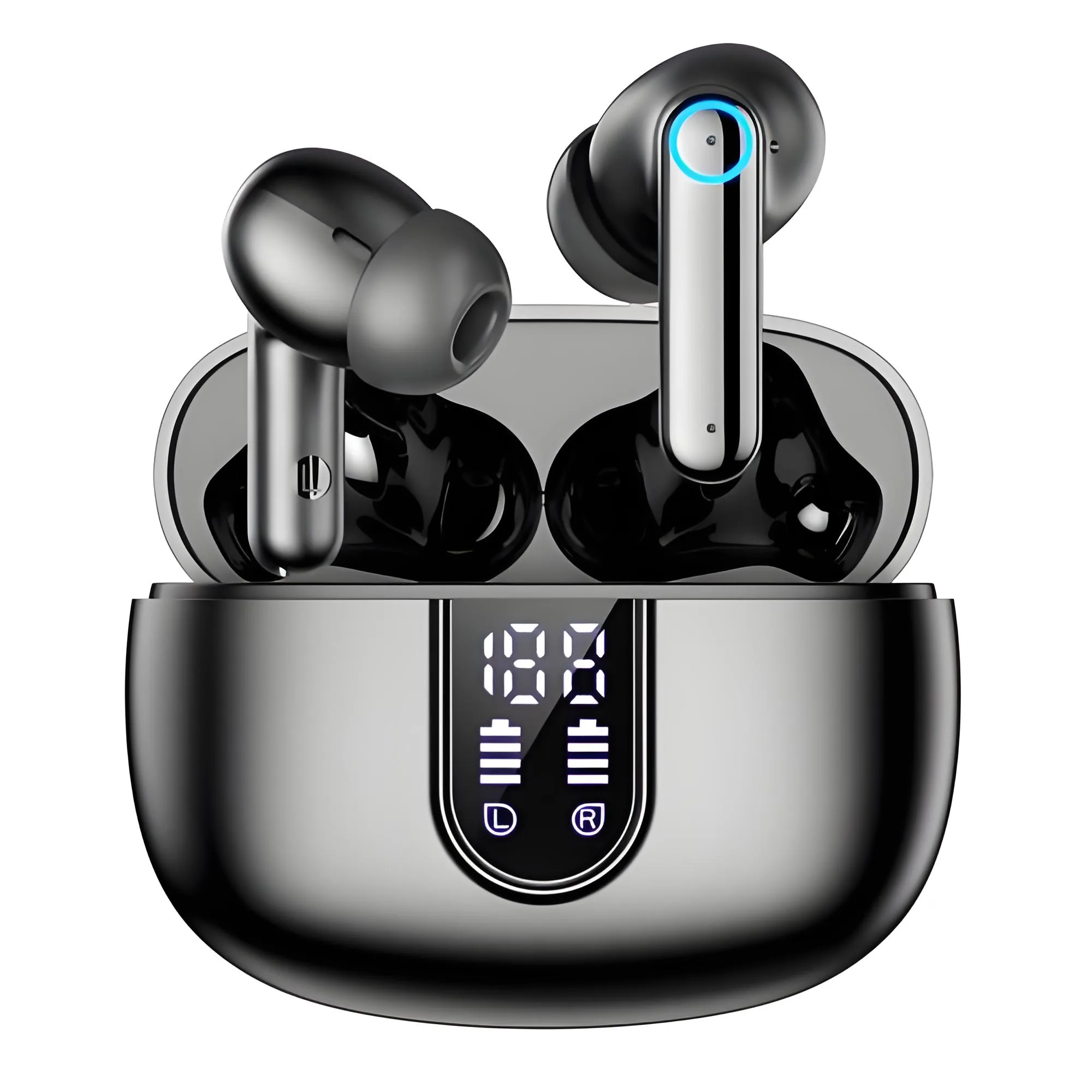
This product primarily serves Bluetooth headset PCB アプリケーション, 特に:
-
TWS True Wireless Bluetooth Earphones: Connecting main control boards with batteries, charging contacts, and microphones.
-
Neckband Sport Bluetooth Earphones: Requiring highly flexible, durable connections between battery compartments and in-line control modules.
-
Smart Wearable Audio Devices: Such as audio connections between smart glasses frames and temples.
これらのアプリケーションで, UGPCB’s rigid-flex boards withstand repeated opening/closing and wearing stresses, ensuring reliable connections throughout product lifespan.
Performance Characteristics and Market Advantages
-
高密度相互接続: 6-layer stack-up accommodates multi-channel I/O routing requirements of modern Bluetooth chips.
-
Three-Dimensional Mounting: Flexible zones fold to utilize irregular earphone internal spaces, enabling thinner, lighter end-product designs.
-
優れた信号の完全性: Immersion gold finish combined with continuous ground planes ensures low-loss RF signal transmission.
-
Shock and Vibration Resistance: Integrated construction eliminates connector loosening risks during drops.
-
コスト効率: Although manufacturing costs exceed standard rigid boards, eliminating connectors and manual assembly operations delivers significant overall cost advantages in volume production.
Power Your Next-Generation Bluetooth Earphone Design—Starting with Premium Rigid-Flex Technology
We recognize that every minute design detail impacts sound quality and battery performance. UGPCB offers not only standardized 6-layer Bluetooth headset rigid-flex boards but also comprehensive services ranging from engineering consultation to volume production. Our engineers will thoroughly review your Gerber files, 保証 0.6mmの厚さ と 4ミル line precision realizes your design intent flawlessly.
Don’t compromise your design due to circuit board limitations.
[Contact UGPCB Today for Samples and Quotations]
Send your PCB files to our email or click the inquiry button below. UGPCB sales engineers will provide professional DFM analysis and competitive volume pricing within 24 時間.


