그리고,PCB, PCBA 및 PECVD 맞춤화, 프로토타이핑 및 제조 생산자

다운로드 | 에 대한 | 연락하다 | 사이트맵

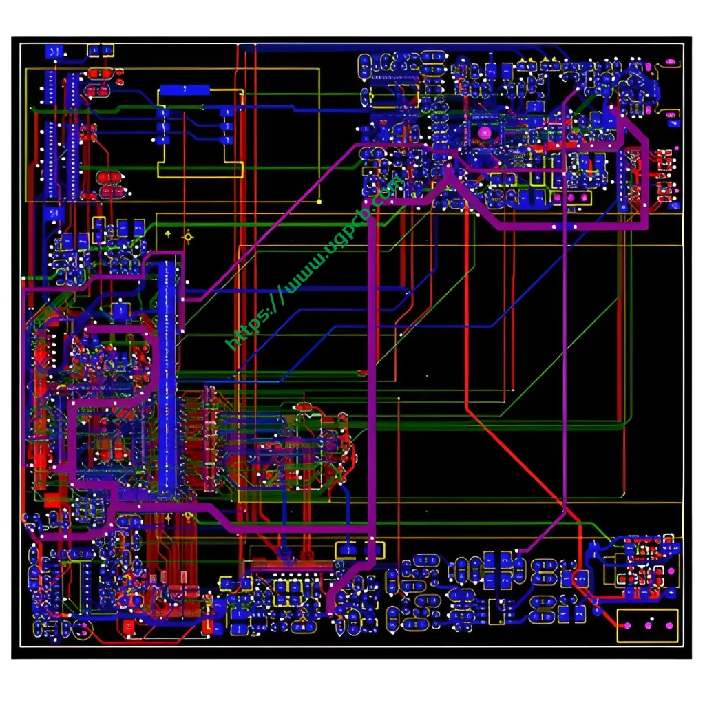
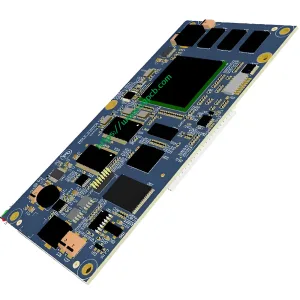
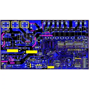
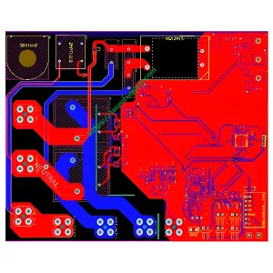
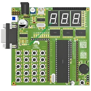
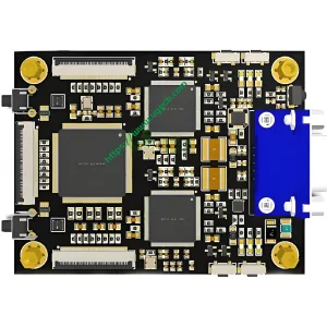
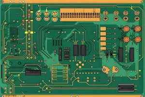
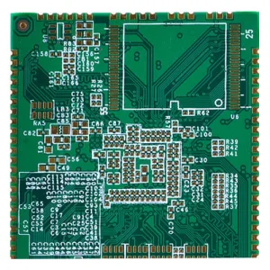
8-레이어 통신 PCB/PCBA 설계 - 그리고

다층 PCB 설계/

8-레이어 통신 PCB/PCBA 설계

이름: 8-레이어 통신 PCB/PCBA 설계

시트: IT180, F4BM, FR4, FR1-4, 등.

디자인 가능한 레이어: 1-32 레이어

최소 줄 너비 및 줄 간격: 3밀

최소 레이저 조리개: 4밀

최소 기계적 조리개: 8밀

동박 두께: 18-175cm (기준: 18cm35cm70cm)

박리강도: 1.25N/mm

최소 펀칭 구멍 직경: 단면: 0.9mm/35mil

최소 구멍 직경: 0.25mm/10mil

조리개 허용 오차: ≤Φ0.8mm±0.05mm

  • 제품 세부정보

Communications PCBs Applications

Communications PCBs are also used in general telecommunications systems such as cell towers, satellites, high-speed routers and servers, and commercial telephony. Telecom PCBs are also frequently used to control LED displays and indicators.

Structure and Composition of High-Frequency Hybrid Splint

Base Plate and Wire Layers

The high-frequency hybrid splint includes a base plate, which is folded and positioned on the first inner wire layer, the first outer wire layer, and the top surface of the solder mask ink layer from top to bottom in order from bottom to top.

Solder Resist Ink Layer and Substrate Areas

The second layer of solder resist ink layer, the substrate includes a high-frequency area and an auxiliary area. The auxiliary area is finally fixed, and the inlay in the high-frequency area should be located at a fixed position.

Functionality and Material Usage

Utility Model Description

The utility model provides a high-frequency hybrid splint, which is divided into two parts: a high-frequency area and an auxiliary area. It provides mechanical support.

High-Frequency Area Arrangement

The utility model discloses that the high-frequency area is independently arranged, and only the high-frequency area is made of high-frequency materials. Under the condition of satisfying high-frequency signals, the use of high-frequency board materials is minimized and the production cost is reduced.

이전:

다음:

답장을 남겨주세요

메시지를 남겨주세요