그리고,PCB, PCBA 및 PECVD 맞춤화, 프로토타이핑 및 제조 생산자

다운로드 | 에 대한 | 연락하다 | 사이트맵

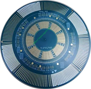
ATE 로드보드 PCB - 그리고

IC 기판/

ATE 로드보드 PCB

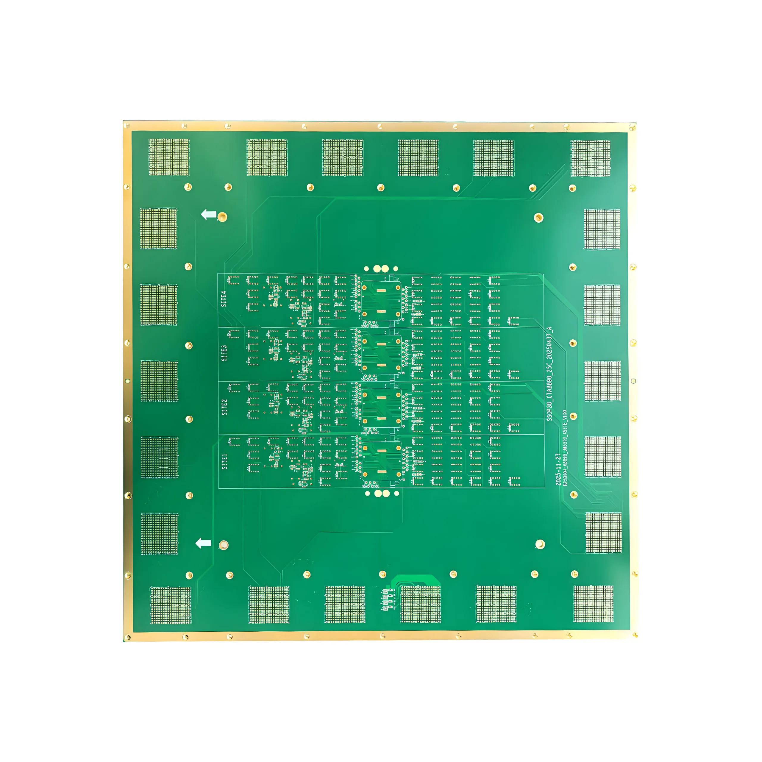
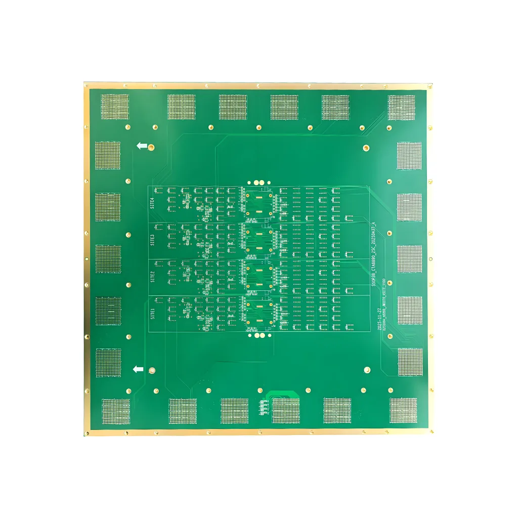
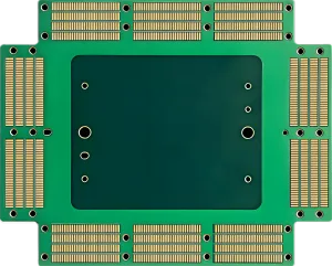
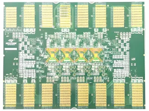
모델 : ATE 로드보드 PCB

재료 : TUC/TU872HF

층 : 28레이어

색상 : 노란색

보드 두께: 5.0mm

표면 기술: hard gold 3-15u

구리 두께: inner layer 2OZ, outer layer 2OZ

특수공정: metal cladding, depth control drilling

애플리케이션 : ATE 로드보드 PCB

  • 제품 세부정보

ATE Load board PCB Overview

The ATE Load board PCB is a highly specialized printed circuit board designed for use in automated test equipment (ATE) 시스템. This advanced PCB supports the testing of electronic components and systems by simulating real-world loads. Below is a comprehensive introduction to the ATE Load board PCB, covering its general information, 분류, 재료, 성능, 구조, 특징, 생산 과정, and application scenarios.

분류

ATE Load board PCBs are classified based on their complexity, layer count, and specific application requirements. The model introduced here, ATE 로드보드 PCB, is a 28-layer PCB, indicating its high complexity and capacity to handle intricate testing scenarios.

재료 구성

The ATE Load board PCB is constructed using TUC/TU872HF material, a high-performance substrate known for its excellent electrical and mechanical properties. This material ensures the PCB’s reliability and durability under demanding test conditions.

성능 특성

The ATE Load board PCB excels in several performance areas, including high current carrying capacity, low signal loss, and excellent thermal management. The use of 2OZ copper thickness for both inner and outer layers enhances its electrical conductivity and thermal dissipation capabilities. 추가적으로, the hard gold 3-15u surface finish provides superior corrosion resistance and solderability.

구조 설계

Structurally, the ATE Load board PCB features a board thickness of 5.0mm, providing a robust foundation for the complex circuitry and components. The yellow color not only adds a visual distinction but also aids in inspection and troubleshooting processes.

독특한 특징

The ATE Load board PCB stands out with its unique features, including metal cladding for enhanced thermal conductivity and depth control drilling for precise component placement and interconnection. These features, combined with its high layer count and advanced materials, make it an ideal choice for ATE applications.

생산 과정

The production of ATE Load board PCBs involves a series of sophisticated steps:

  1. 재료 준비: The TUC/TU872HF substrate is prepared and cut to the required dimensions.
  2. Copper Lamination: Copper foil is laminated to the substrate, with specific attention to the 2OZ thickness requirement.
  3. Circuit Patterning: The desired circuit patterns are etched onto the copper foil using precision etching techniques.
  4. Layer Stacking and Lamination: Multiple layers are stacked and laminated together, ensuring precise alignment and bonding.
  5. Drilling and Plating: Depth control drilling is performed to create holes for component mounting and interconnection. The holes are then plated to enhance conductivity.
  6. Metal Cladding: A metal layer is applied to the PCB surface to improve thermal conductivity and mechanical strength.
  7. Surface Finish Application: The hard gold 3-15u coating is applied to provide corrosion resistance and solderability.
  8. Final Inspection and Testing: The PCB undergoes rigorous inspection and testing to ensure compliance with specifications and performance requirements.

응용 시나리오

ATE Load board PCBs are primarily used in automated test equipment systems for the testing and validation of electronic components and systems. They are essential in the semiconductor industry, 자동차 산업, aerospace industry, and other sectors where high-reliability testing is crucial. By simulating real-world loads, ATE Load board PCBs enable engineers to verify the performance and reliability of electronic devices before they are deployed in actual applications.

이전:

답장을 남겨주세요

메시지를 남겨주세요