그리고,PCB, PCBA 및 PECVD 맞춤화, 프로토타이핑 및 제조 생산자

다운로드 | 에 대한 | 연락하다 | 사이트맵

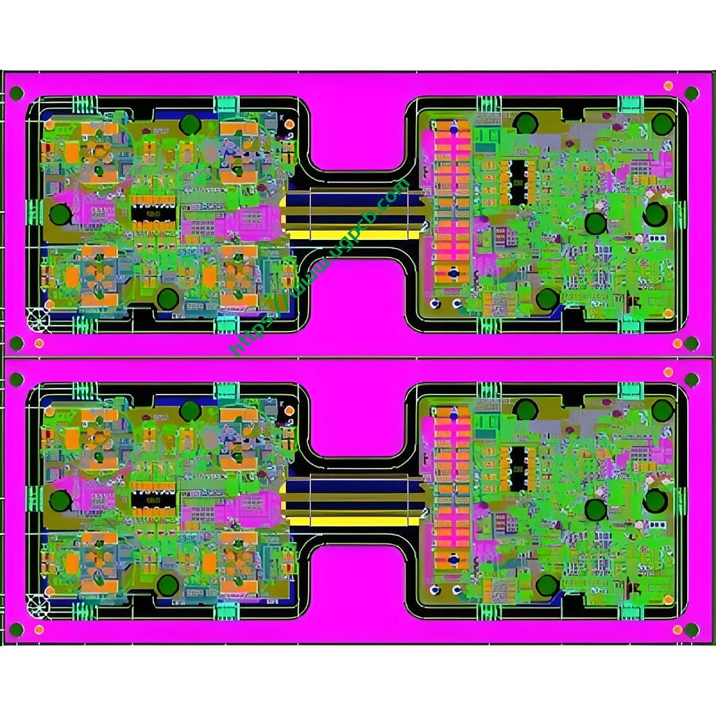
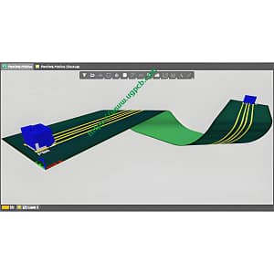
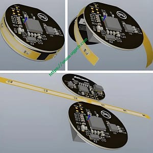
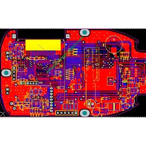
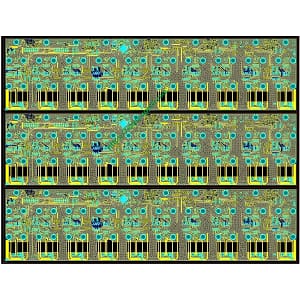
HDI Rigid-Flex PCB Layout & 설계 - 그리고

견고한 플렉스 PCB 설계/

HDI Rigid-Flex PCB Layout & 설계

이름: HDI Rigid-Flex PCB Layout & 설계

디자인 가능한 레이어: 1-32 레이어

최소 줄 너비 및 줄 간격: 3밀

최소 레이저 조리개: 4밀

최소 기계적 조리개: 8밀

동박 두께: 18-175cm (기준: 18cm35cm70cm)

박리강도: 1.25N/mm

최소 펀칭 구멍 직경: 단면: 0.9mm/35mil

최소 구멍 직경: 0.25mm/10mil

조리개 허용 오차: ≤Φ0.8mm±0.05mm

Hole tolerance: ±0.05mm

  • 제품 세부정보

Definition of HDI PCB

고밀도 상호 연결 (HDI) is simply a PCB with a higher number of interconnects in the smallest footprint. This leads to miniaturization of the circuit board. Components are placed closer together and board space is significantly reduced, but functionality is not compromised.

More precisely, a PCB with an average of 120 에게 160 pins per square inch is considered an HDI PCB. HDI designs combine dense component placement and versatile routing. HDI popularized microporous technology by implementing microvias, buried vias, and blind vias. Reduced drilling of copper is a feature of HDI designs.

Advantages of HDI PCB

Extraordinary Versatility

HDI boards are ideal when weight, space, 신뢰할 수 있음, and performance are the main concerns.

Compact Design

The combination of blind, buried, and micro vias reduces board space requirements.

Better Signal Integrity

HDI utilizes via-in-pad and blind via technology. This helps keep components close to each other, reducing signal path lengths. HDI technology removes through-hole stubs, thus reducing signal reflections, thereby improving signal quality. 그러므로, it significantly improves signal integrity due to shorter signal paths.

높은 신뢰성

The implementation of stacked vias makes these boards a super barrier against extreme environmental conditions.

Cost-effective

The functionality of a standard 8-layer through-hole board (standard PCB) can be reduced to a 6-layer UGPCB board without compromising the quality.

다음:

답장을 남겨주세요

메시지를 남겨주세요