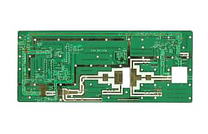
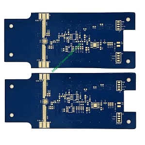
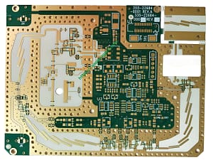
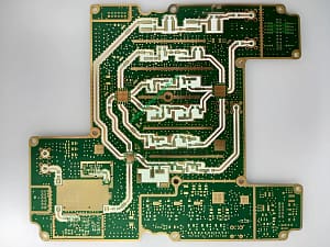
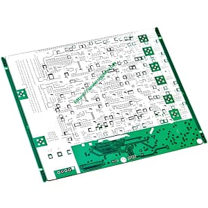
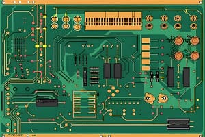
고주파 마이크로파 PCB의 정의
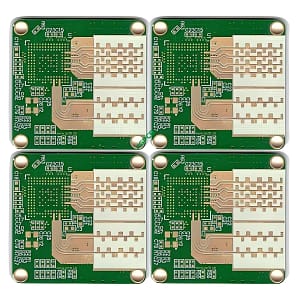
고주파 마이크로파 회로 보드는 특수 전자기 주파수 회로 보드를 의미합니다., 고주파에 사용됩니다 (이상 300 MHz 주파수 또는 파장보다 1 미터) 그리고 전자레인지 (이상 3 GHZ 주파수 또는 파장보다 0.1 미터) PCB 필드에서. CCL. 일반적으로 말하면, 고주파 PCB 보드는 1GHz 회로 보드보다 높은 주파수로 정의 할 수 있습니다..
과학과 기술의 급속한 발전으로, 점점 더 많은 장치가 마이크로파 주파수 대역으로 설계되었습니다. (>1GHz) 또는 밀리미터 파 필드 (30GHz) 응용 프로그램 위, 또한 주파수가 점점 높아지고 있음을 의미합니다., 그리고 회로 보드 기판에 미치는 영향도 요구 사항도 높아지고 있습니다.. 예를 들어, 기판 재료는 우수한 전기 성능을 가져야합니다, 좋은 화학적 안정성, 전력 신호 주파수가 증가함에 따라, 기판 손실에 대한 요구 사항도 매우 작습니다., 따라서 고주파 보드가 강조 표시됩니다.
PCB 고주파 전자 레인지 회로 보드 단일 보드 응용 프로그램 필드
1. 모바일 커뮤니케이션 제품, 스마트 조명 시스템
2. 전력 증폭기, 저잡음 증폭기, 등.
3. 수동 장치, 전력 분배기와 같은, 커플러, 듀플렉서, 필터, 등.
4. 자동차 충돌 회피 시스템의 분야에서, 위성 시스템, 무선 시스템, 등., 전자 장비의 개발 추세는 고주파입니다.
고주파 전자 레인지 PCB 보드의 분류
충전 된 분말 세라믹을위한 써모셋 재료
제조업체: 로저스 4350B/4003C, 25Taconi Corporation TLG 시리즈 Arlon의 N/25fr
접근하다:
이 과정은 에폭시/유리 직물 천과 유사합니다 (FR4), 그러나 접시는 부서지기 쉽고 쉽게 부러집니다.
구멍과 공판을 시추 할 때, 드릴 비트와 공 나이프의 수명은 20%.
PTFE (폴리테트라플루오로에틸렌), 폴리테트라플루오로에틸렌 PCB.
제조업체
1. RO3000 시리즈, RT 시리즈 및 TMM 시리즈 Rogers Corporation
2. Arlon의 AD/AR 시리즈, Isoclad 시리즈 및 Cuclad 시리즈
3. 타코니 RF 시리즈, TLX 시리즈 및 TLY 시리즈
4. 도균 전자 레인지 F4B, F4BM, F4BK, TP-2
처리 방법
1. 절단 보드: 흠집과 들여 쓰기를 방지하기 위해 보호 필름을 유지해야합니다.
2. 운동:
에이. 새 드릴 비트를 사용하십시오 (기준 130), 바람직하게는 스택에 하나, 40psi의 압력 압력으로
비. 커버 시트로서 알루미늄 시트, 그런 다음 1mm를 사용하십시오 3 오라 민 패드로 테플론 시트를 조입니다
기음. 시추 후, 공기 건을 사용하여 구멍의 먼지를 날려 버립니다.
디. 가장 안정적인 드릴링 및 드릴링 매개 변수를 사용하십시오 (원래, 구멍이 작을수록, 드릴링 속도가 빨라집니다; 칩 부하가 낮아집니다, 수익률이 낮습니다)
3. 구멍 처리
1. 혈장 처리 또는 나트륨 나프탈렌 활성화 처리는 기공의 금속 화에 유리합니다.
4. 부갑상선 호르몬
에이. 마이크로 에칭 후 (마이크로 에칭 속도는 제어됩니다 20 마이크로 인치), 보드는 PTH의 De-Cylinder에서 공급되어야합니다.
비. 필요한 경우 두 번째 PTH가 수행됩니다, 예상 마가리토프 항아리로 시작하십시오
5. 솔더 마스크
에이. 전처리: 기계식 분쇄판 대신 산세 판을 사용하십시오
비. 전처리, 그런 다음 보드를 굽습니다 (90 섭씨도, 30 분), 치료하기 위해 녹색 기름으로 브러시
기음. 베이킹 팬이 나뉘어져 있습니다 3 부분품: 한 부분은 80 섭씨도, 100 섭씨 온도와 150 섭씨도, 각 부분의 시간은 30 분입니다 (기판 표면에 오일이 쏟아져있는 경우, 재 작업 할 수 있습니다: 녹색 기름을 씻고 다시 시작하십시오)
6. 윤곽 라우팅
PTFE 보드 회로 표면에 백서를 뿌립니다., 구리를 제거하기 위해 FR-4 기질 또는 페놀 기판으로 상단과 하단을 1.0mm로 클램핑하십시오.: 그림에서 볼 수 있듯이:
7. 프로세스 흐름
A.NPTH PTFE 시트 처리 기술
데이터 드릴링 – 교련 – 마른 필름 – 점검 – 에칭 – 에칭 – 솔더 저항 – 캐릭터 – 주석 스프레이 – 형성 – 테스트 – 최종검사 – 포장 – 해운
B.PTH PTFE 시트 처리 기술
재료 오프닝 – 교련 – 시추 처리 (혈장 처리 또는 질화 나트륨 활성화 처리) – 구리 침전 – 보드 전기 – 드라이 필름 – 점검 – 전기를 당기십시오 – 에칭 – 부식 검사 – 솔더 저항 – 성격 – 주석 분사 – 형성 – 테스트 – 최종검사 – 포장 – 해운
8. 요약
고주파 회로 보드 처리의 어려움
에이. 구리 싱크: 구멍 벽은 구리 도금되기 쉽지 않습니다
비. 전환, 에칭, 선 너비 슬롯, 모래 구멍 제어
기음. 녹색 오일 공정: 녹색 오일의 접착력과 거품을 제어하십시오
디. 각 프로세스에서 PCB 보드의 흠집을 엄격하게 제어합니다, 등
올바른 전자 레인지 PCB 제조업체를 선택 해야하는 이유?
전자 레인지 PCB 제조업체의 마이크로파 PCB 보드 주문 첨단 장비가 장착 된 저렴한 PCB 제조업체는 저수준 재료를 사용하는 저비용 PCB 제조업체에 더 유리합니다..
마이크로파 PCB는 노이즈와 같은 요인에 매우 민감합니다., 임피던스, 전자기 및 ESD. 고품질 PCB의 제조업체는 제조 공정의 기여 요인을 제거하는 데 중점을 둡니다.. 저품질 RF 전자 레인지 회로 보드는 오랫동안 발생하지 않을 것으로 예상되지 않습니다., 그렇기 때문에 완벽한 RF 전자 레인지 회로 보드 제조업체를 선택하면 제품 경험을 바꿀 수 있습니다..
오늘, 대부분의 최신 RF 마이크로파 PCB 제조업체는 PCB 제작에 컴퓨터 보조 엔지니어링 소프트웨어 아날로그 프로그램을 사용합니다.. CAD 기반 RF 전자 레인지 PCB 제조의 가장 큰 장점은 적절한 제품 사양이있는 다양한 브랜드 및 PCB 모델의 시뮬레이션 모델을 가지고 있다는 것입니다..
이러한 매개 변수는 RF 마이크로파 PCB의 생산을 표준화하고 신뢰성을 보장하는 데 중요합니다.. 게다가, 이 기계는 또한 수동 작동을 지원합니다, 운영자가 수동 작업을 수행 할 수 있습니다.
이 시점에서, RF 전자 레인지 PCB의 제조가 간단하지 않다는 것은 분명합니다..
RF 마이크로파 PCB를 제조하기 위해 UGPCB를 선택하는 이유는 무엇입니까??
UGPCB는 수년 동안 RF 마이크로파 PCB 제조 시설을 제공했습니다.. UGPCB의 자격을 갖춘 전문가는 Rogers를 기반으로 한 PCB 제조 전문 지식을 보유하고 있습니다. (Taconic PCB 재료). 다행스럽게도, UGPCB는 통신 장비를위한 RF 마이크로파 PCB 제조에 풍부한 경험을 가지고 있습니다..
UGPCB는 RF 마이크로파 PCB 제조에 사용되는 경향이 있습니다.. 다양한 마이크로파 PCB 재료는 요구 사항에 따라 가장 적합한 재료를 선택할 수 있습니다..
UGPCB를 통해 RF 마이크로파 PCB를 만드는 이점.
RF 마이크로파 PCB는 일반 PCB만큼 제조하기 쉽지 않습니다.. 자세히 설명하고 모니터링해야합니다.. 숙련 된 RF 마이크로파 PCB 제조업체로서, UGPCB. UGPCB는 세계적으로 유명한 PCB 제조 브랜드입니다. 고품질 제품과 만족스러운 고객 경험은 우리의 이미지를 향상시킵니다.
전자 레인지 PCB 제조업체가 제품을 사용한다고 믿기 어렵습니다., 우리는 이것을 진정으로 이해합니다. UGPCB는 제조 공정에서뿐만 아니라, 또한 마이크로파 회로 보드 제조 후에도 상세한 기술 지원을 제공합니다.
우리는 당신의 마이크로파 PCB가 제조 될뿐 아니라, 그러나 제품은 필요에 따라 정확히 기능합니다. 제조 전, 그들은 전체 설계를 분석하여 가능한 결함이나 개선이 있는지 확인합니다.. 그래서, 우리는 고객의 문제를 고려하고 신뢰할 수있는 제품을 개발할 것입니다..
디자인에 사양이 없거나 필요한 기능이없는 경우, UGPCB 팀은 대안을 제공하기 위해 고객과 논의 할 책임이 있습니다.. 또한, 테스트 팀이 사용자 정의 RF 전자 레인지 회로 보드에서 다양한 테스트를 수행하므로 고객은 바쁜 테스트를 피할 수 있습니다. – 마이크로파 PCB가 목적을 달성하는지 확인하십시오.
 UGPCB 로고
