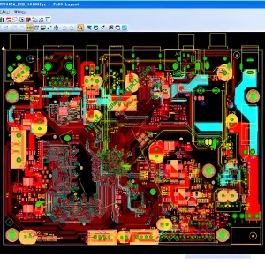
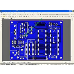
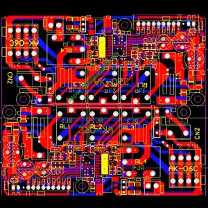
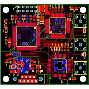
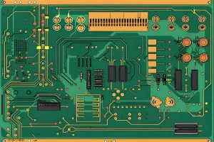
RF PCB 설계 개요
RF PCB 설계 소개
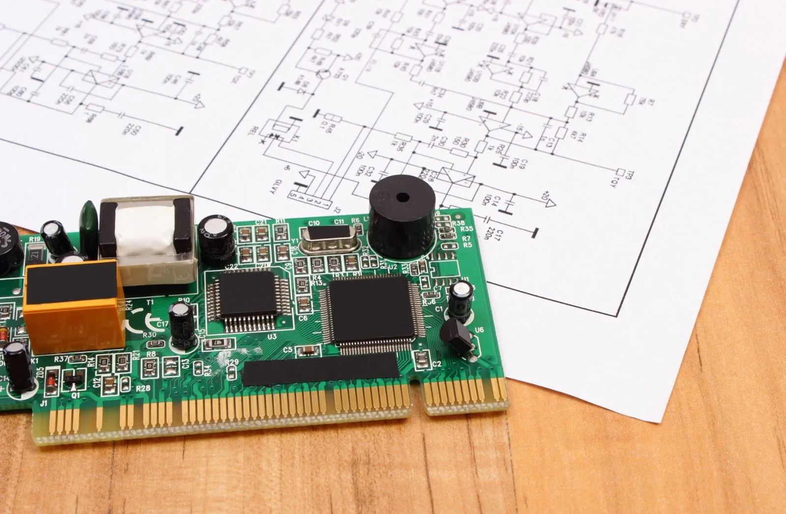
무선 통신 시스템에서, 프론트 엔드 회로의 작은 부분 만 무선 주파수 단계에서 작동합니다., 일반적으로 무선 주파수 프론트 엔드 회로라고합니다.. 나머지 회로는 저주파베이스 밴드 아날로그 및 디지털 신호 처리에 사용됩니다.. RF 프론트 엔드 회로에는 일반적으로 저음 증폭기가 포함됩니다, 믹서, 전력 증폭기. 회로 의이 부분의 구성 요소 수는베이스 밴드 회로의 구성 요소보다 훨씬 적습니다., 여전히 전체 시스템의 성공 또는 실패의 열쇠입니다..
주요 지표 및 설계 과제
아날로그 IC 설계의 팔각형 규칙과 유사합니다, RF PCB 설계에는 넓은 동적 범위 및 고주파수에서 아날로그 신호 처리가 필요합니다.. 그러므로, RF PCB 디자인에는 고유 한 육각 규칙이 있습니다. 소음, 선형성, 공급 전압, 얻다, 작동 주파수, 전력은 RF PCB에서 가장 중요한 메트릭입니다.. 실용적인 디자인, 이러한 매개 변수 중 하나 이상이 서로 구속됩니다., 다차원 최적화 문제가 발생합니다. 이러한 타협과 상호 제약은 RF PCB의 설계에 많은 문제를 가져옵니다.. 자주, 더 나은 타협에 도달하려면 RF 디자이너의 직관과 경험이 필요합니다..
RF PCB의 응용 분야
RF PCB의 다양한 응용
- 기지국 RF 회로 보드
- 휴대폰 RF 회로 보드
- 무선 지역 영역 네트워크 (wlan) RF PCB
- 글로벌 포지셔닝 시스템 (GPS) RF 회로 보드
- 무선 주파수 태그 (RFID) RF PCB
- 사물 인터넷 (IoT) RF PCB
 UGPCB 로고
