
Introduction

In modern electronics manufacturing, Surface Mount Technology (SMT) has become the core process for PCB assembly. However, as component sizes continue to shrink and soldering processes become more complex, the reliability of solder joint strength has become increasingly critical. Solder joint strength not only directly impacts the mechanical performance of products but also determines their long-term reliability in harsh environments. This article explores the specifications and evaluation criteria for pull and shear testing of SMT component solder joint strength through detailed experimental data and professional analysis, providing scientific insights and practical guidance for the industry.
Experimental Methods and Design
Experimental Design
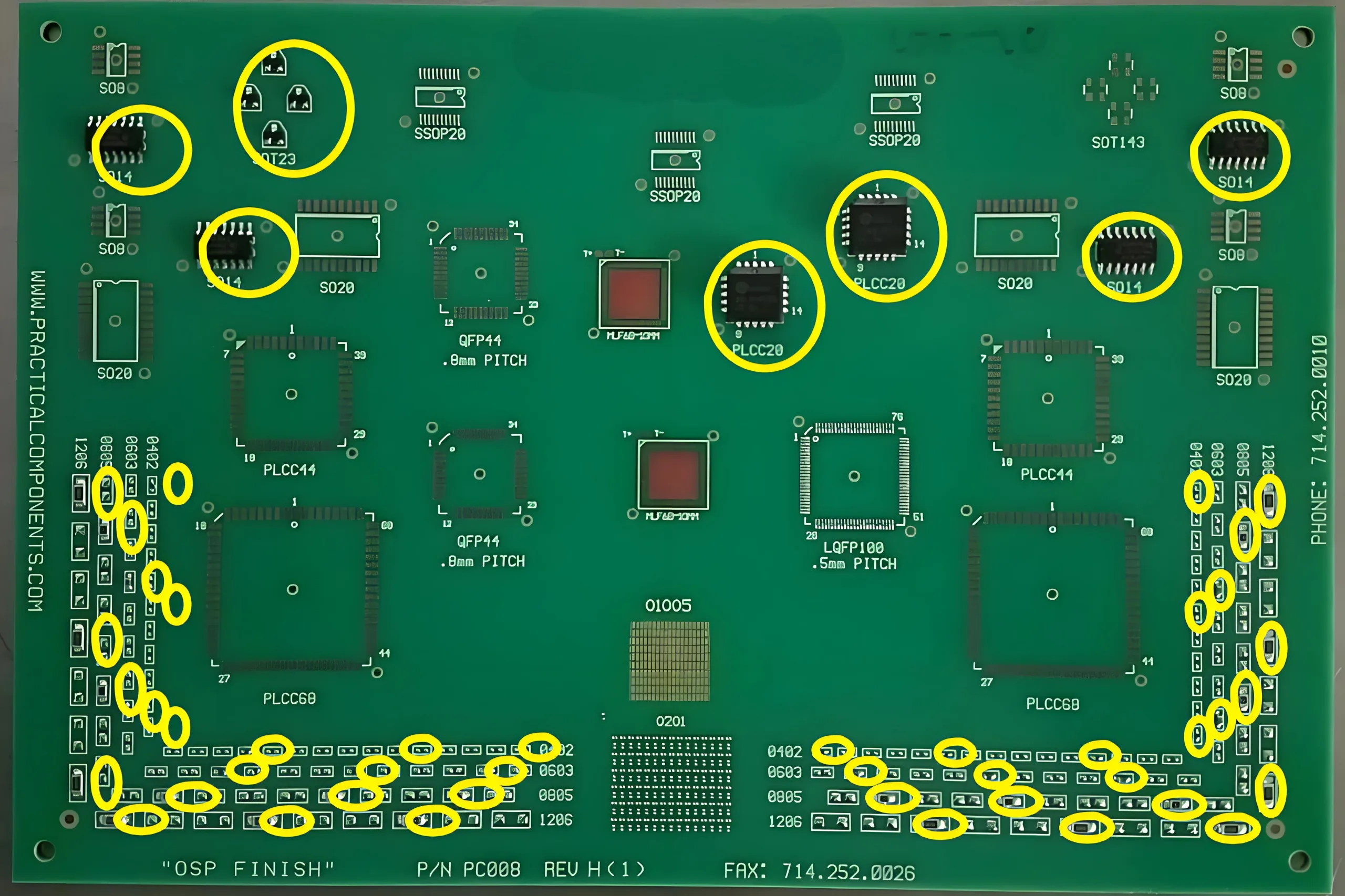
The experiment selected a variety of common SMT components, including passive components such as 0402, 0603, 0805, and 1206, as well as leaded components like SOT23, SO14, and PLCC20. By adjusting solder paste volume, stencil thickness, and printing parameters, different soldering conditions were simulated to evaluate the factors affecting solder joint strength.
Solder Paste Volume and Stencil Design

Solder paste volume is one of the key factors influencing solder joint strength. The experiment designed a gradient of solder paste volumes ranging from 25% to 125%, combined with different stencil thicknesses (51µm to 102µm), to study the relationship between solder paste transfer efficiency and solder joint strength. Experimental data showed that reducing solder paste volume significantly decreases solder joint strength, especially for passive components, where a 50% solder paste volume approaches the lower acceptable limit.
Formula: Solder Paste Transfer Efficiency = (Actual Solder Paste Volume / Stencil Aperture Volume) × 100%
For example, the transfer efficiency for a 0402 component at 25% solder paste volume was 31%, while at 125%, it reached 138%. This data provides critical insights for optimizing solder paste printing processes.
Printing Parameters and Reflow Profile
Parameters such as printing speed, squeegee pressure, and separation speed significantly affect the uniformity and transfer efficiency of solder paste. The experiment employed a printing speed of 30 mm/sec, a squeegee pressure of 5.0 kg, and a 10-zone reflow oven to ensure process control. Key parameters of the reflow profile included:
- Soak Time (150-200°C): 70-75 seconds
- Time Above Liquidus (>221°C): 63-70 seconds
- Peak Temperature: 243-249°C
These parameters ensured proper solder joint formation while avoiding defects caused by overheating.
Results and Discussion
Solder Joint Strength Testing
Pull and shear tests were conducted to evaluate the solder joint strength of different components. For example:
- 0402 Component: The required shear force standard was ≥0.65Kgf. Experimental data showed a shear force of 0.68Kgf at 50% solder paste volume, close to the acceptable threshold.
- 1206 Component: The required shear force standard was ≥3.00Kgf. Experimental data showed a shear force of 3.15Kgf at 100% solder paste volume, demonstrating good performance.
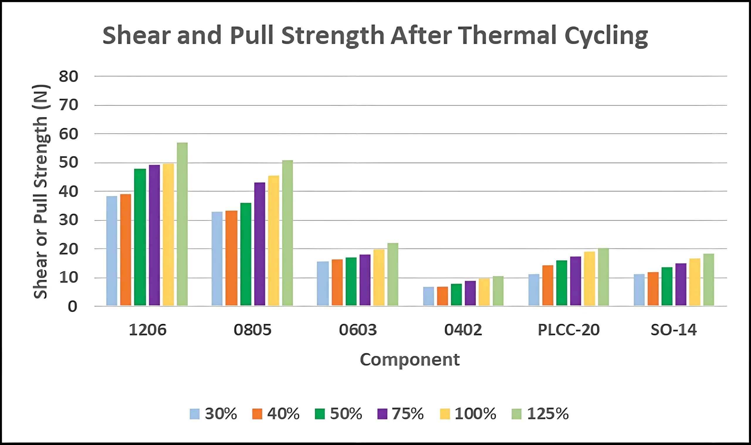
Impact of Thermal Cycling on Solder Joint Strength
The experiment also simulated thermal cycling conditions (-40°C to 125°C, 1000 cycles) to study the long-term reliability of solder joint strength. Results indicated that thermal cycling significantly reduces solder joint strength, particularly under low solder paste volume conditions. For instance, the shear force for a 0402 component at 25% solder paste volume decreased from 0.68Kgf to 0.55Kgf after thermal cycling, falling below the acceptable standard.
Analysis of Solder Joint Defects
Based on IPC-A-610 and J-STD-001 standards, the experiment conducted a detailed analysis of solder joint defects. Results showed that insufficient solder paste volume (e.g., 25%) led to an increase in defects such as solder balls and skew off pad. For example, the defect rate for solder balls in 0402 components was 17% at 25% solder paste volume but decreased to 3% at 125%.
Conclusions and Recommendations
Optimization of Solder Paste Volume
The experiment demonstrated that solder paste volume significantly impacts solder joint strength. It is recommended that in actual production:
- For passive components, solder paste volume should be maintained above 50% to ensure solder joint strength.
- For leaded components (e.g., PLCC20 and SO14), solder paste volume can be reduced to 40%, but further research is needed for components like SOT23.
Standardization of Process Parameters
Standardizing printing parameters and reflow profiles is crucial for ensuring solder joint strength. Our UGPCB assembly factory customizes detailed process parameter specifications based on equipment and component types, followed by validation and adjustments.
Enhancing Long-Term Reliability
Thermal cycling experiments revealed that solder joint strength gradually declines over time. For applications requiring high reliability, it is recommended to use higher solder paste volumes and optimized PCBA soldering processes to enhance long-term reliability.
Conclusion
Pull and shear testing of SMT solder joint strength is not only a critical quality control measure but also a key factor in improving the reliability of PCBA products. In the future, as component sizes continue to shrink, UGPCB will innovate and research new processes and methods. While serving our customers, we aim to collaborate with industry peers to drive advancements in electronics manufacturing and propel the progress of the PCBA assembly industry.
