
Controle de vazio BGA
No mundo da fabricação de PCB de precisão, cada detalhe é crucial, especialmente quando se trata de BGA (Array da grade de bola) embalagem. Vazios BGA, ou pequenas cavidades dentro de bolas de solda, pode parecer insignificante, mas pode esconder grandes riscos que afetam a confiabilidade do produto. Este artigo irá se aprofundar em como reduzir a ocorrência de vazios BGA através de um controle meticuloso do processo, garantindo a estabilidade e segurança das conexões eletrônicas.
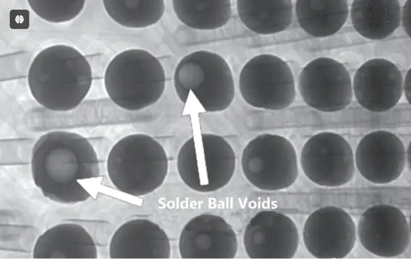
Vazio BGA
A localização dos vazios: O ponto-chave
Primeiro, vamos esclarecer uma coisa: nem todos os vazios são igualmente perigosos. Vazios dentro das bolas de solda, se não representarem uma ameaça direta à integridade estrutural, pode ter impacto limitado. No entanto, quando aparecem espaços vazios na interface entre a esfera de solda e o substrato da embalagem ou a esfera de solda e a PCB, a situação é drasticamente diferente. Esses vazios de interface atuam como potenciais aceleradores de crack; uma vez submetido a forças externas, eles podem causar rachaduras nas juntas de solda, afetando gravemente a confiabilidade e a vida útil do produto.
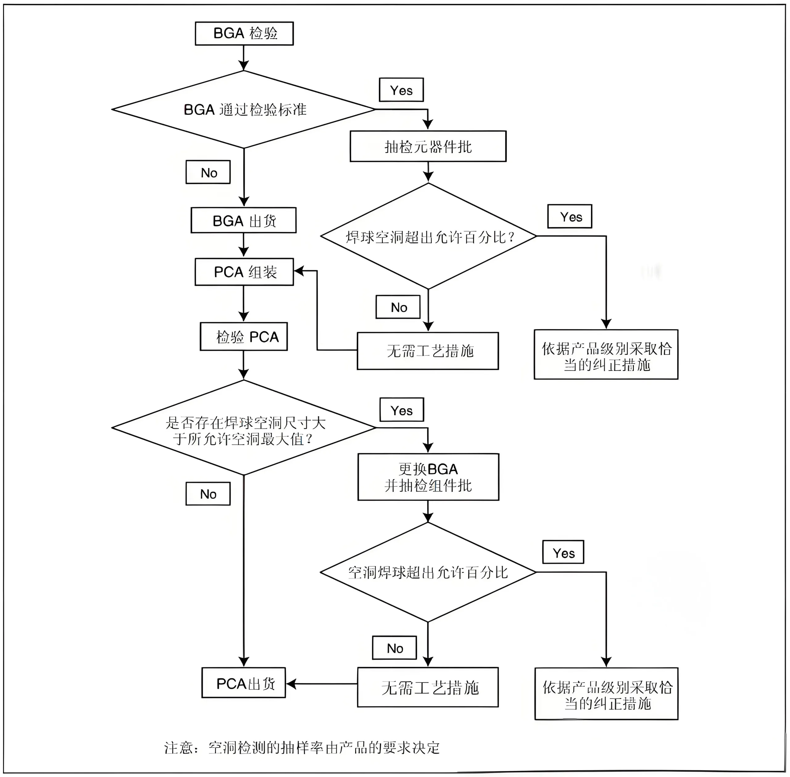
Fluxograma de Avaliação de Vazios
Para compreender intuitivamente o processo de avaliação de vazios, apresentamos a Figura A-1. Este fluxograma detalha cada etapa, desde a identificação de nulos até a tomada de ações correspondentes, servindo como uma ferramenta eficaz para garantir o controle do processo.
Indicadores de medidas corretivas: Ações precisas
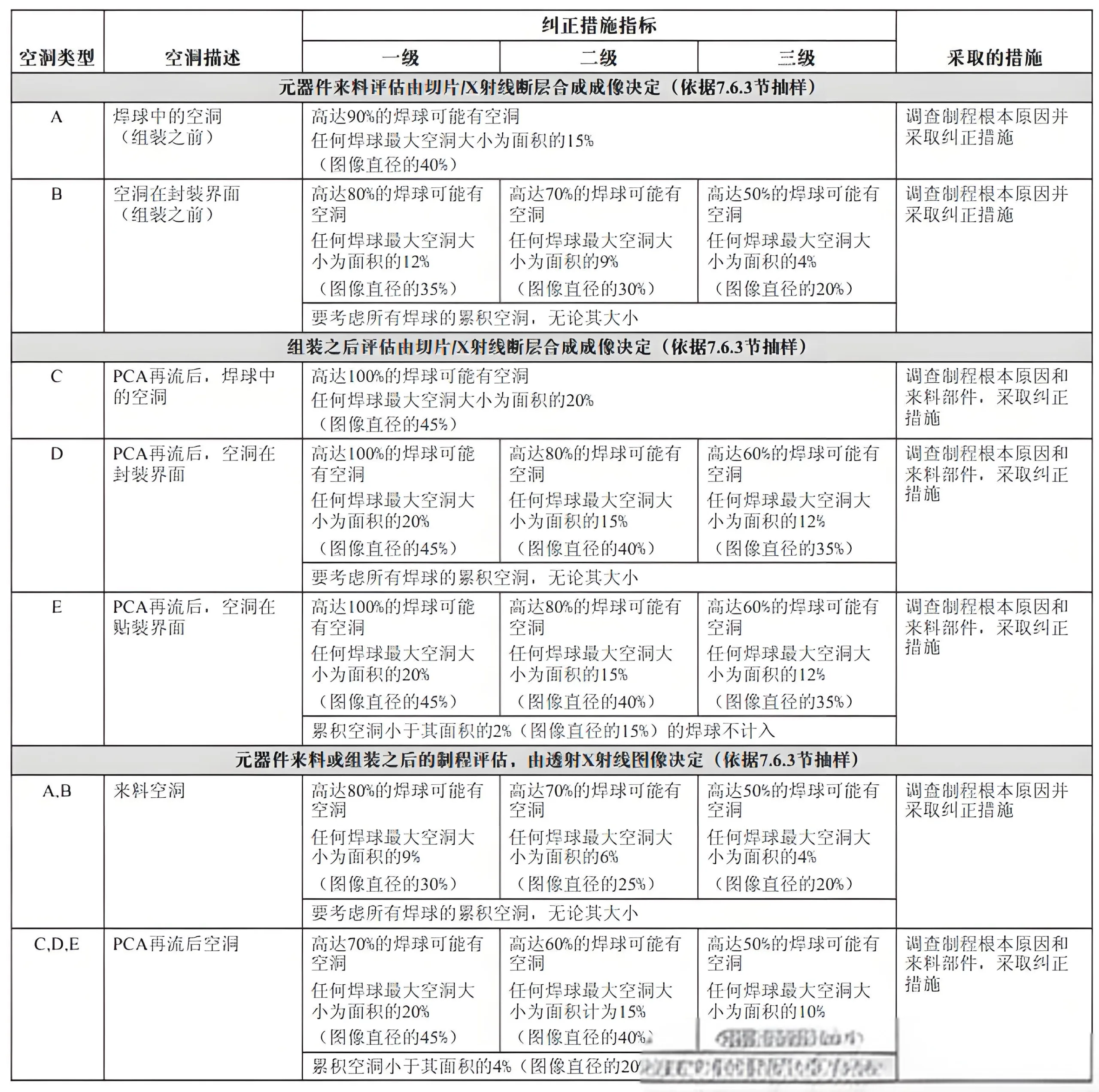
A-1 Índice de medidas corretivas para placas de conexão utilizadas com 1.5, 1.27 ou passo de 1,0 mm
Para BGAs com tons diferentes, desenvolvemos indicadores detalhados de medidas corretivas, conforme mostrado nas Tabelas A-1 a A-3 (cujo conteúdo está resumido aqui em forma de texto). Com base nos padrões IPC, essas tabelas combinam localização nula, tamanho, e quantidade para fornecer diretrizes de ação específicas para BGAs de diferentes tons. Por exemplo, A Tabela A-1 lista as medidas recomendadas para diferentes tipos e quantidades de vazios para BGAs com passos de 1,5 mm, 1.27milímetros, e 1,0 mm, com o objetivo de manter a confiabilidade da conexão.
Descrição da característica do processo: Controle Científico
A descrição das características do processo está no centro da redução de vazios. Com base no tamanho do vazio e seguindo as sugestões do fluxograma, combinado com a estrutura de três níveis nos padrões IPC, considera local vazio, tamanho, e quantidade para estabelecer medidas de controle necessárias. Estas medidas aplicam-se não apenas à otimização contínua de produtos existentes, mas também à introdução de novos produtos., qualificações de produtos e processos, alterações na configuração do equipamento, qualificações de componentes, e respostas de feedback do cliente.
Desafios e respostas ao BGA de pitch fino
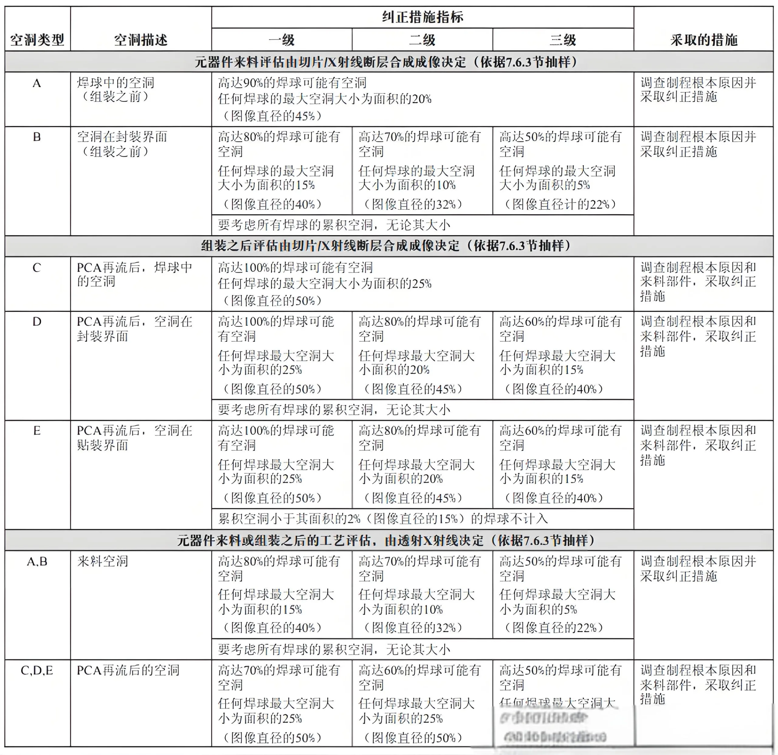
A-2 Índice de medidas corretivas para placas de conexão utilizadas com 1.5, 1.27 ou passo de 1,0 mm
À medida que o tom do BGA continua a diminuir, o mesmo acontece com a área de conexão, colocando maiores demandas no controle de vazios. A Tabela A-2 aborda especificamente BGAs com passos de 0,8 mm, 0.65milímetros, e 0,5 mm, fornecendo medidas corretivas detalhadas. Para BGAs de afinação fina, mesmo pequenos vazios podem afetar significativamente a confiabilidade da conexão. Portanto, medidas de controle mais rigorosas, como reduzir o tamanho do vazio, deve ser tomado para compensar a diminuição da área de conexão.
Design Via-in-Pad e controle de vazio
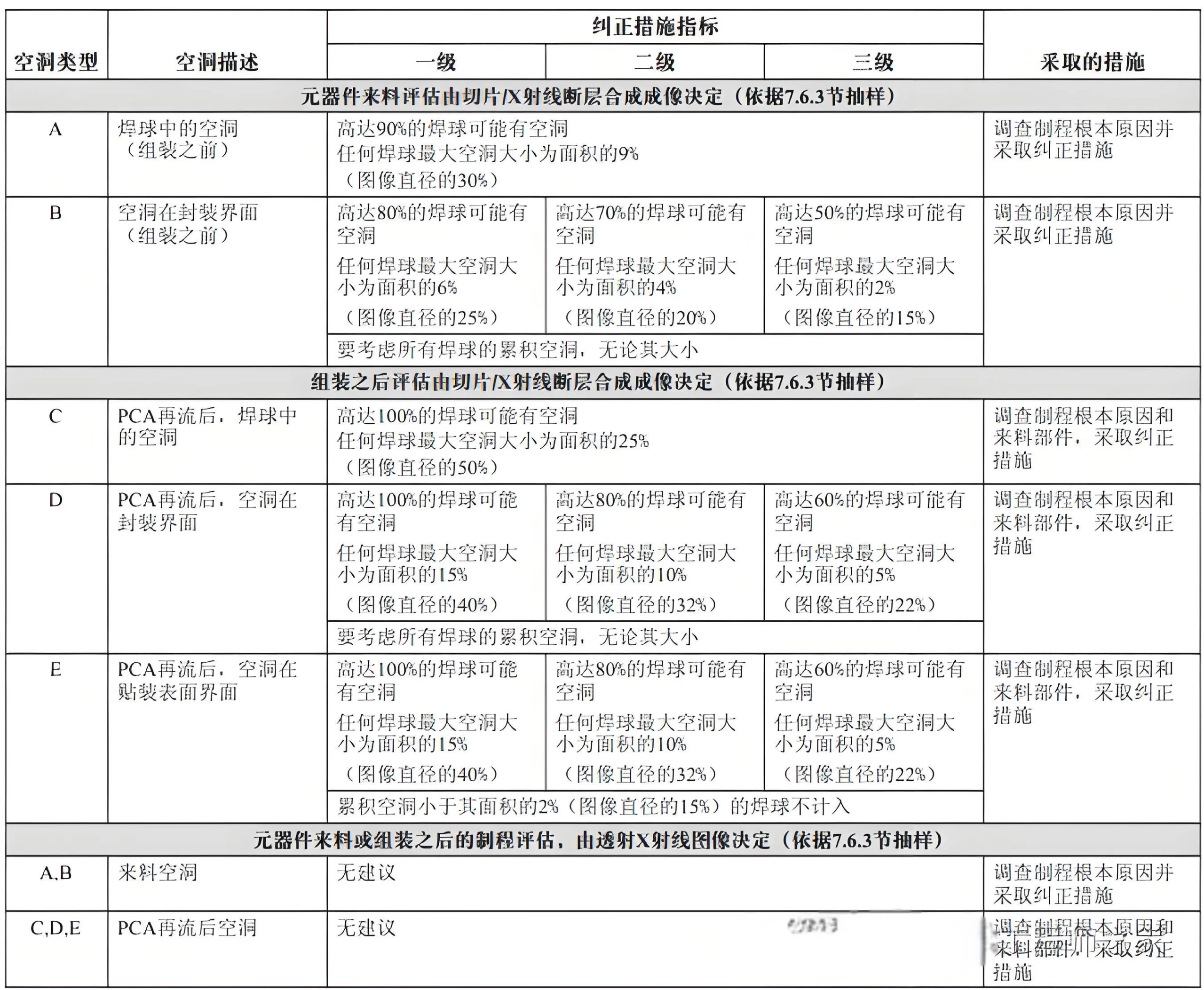
A-3 Índice de medidas corretivas para placas de conexão utilizadas com 1.5, 1.27 ou passo de 1,0 mm
Em projetos com passos menores, Projetos de microvias e via-in-pad tornam-se essenciais para obter espaço de roteamento suficiente. No entanto, isso introduz novos desafios: como garantir que esses projetos não aumentem o risco de vazios? Figura A-2 (imagine um esquema mostrando como as rachaduras podem se propagar a partir de vazios) demonstra como os vazios podem afetar a confiabilidade da junta de solda. Para evitar isso, projetos via-in-pad exigem restrições adicionais nas tolerâncias de vazios, conforme mostrado na Tabela A-3.
Anular padrões de controle de processo
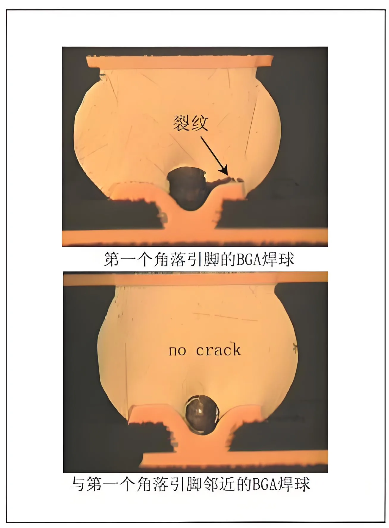
Vazio no BGA
O tamanho e a quantidade de vazios são indicadores importantes para avaliar a eficácia do controle do processo. A ocorrência rotineira de vazios indica uma perda de controle do processo, necessitando de ferramentas necessárias para melhorar processos e materiais. Com base no tamanho e passo, definimos características aceitáveis de vazios para garantir a confiabilidade do produto final.
Detalhes determinam o sucesso ou o fracasso: Consideração do formato da bola de solda
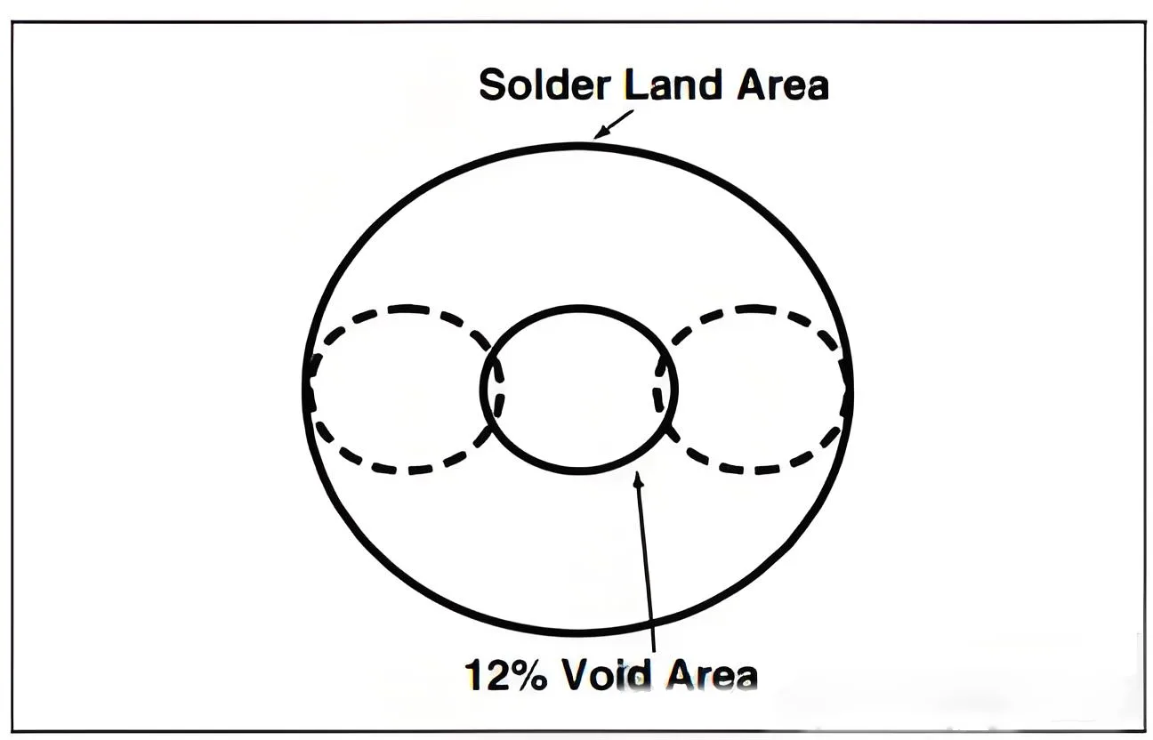
Por último, o impacto do formato da bola de solda no controle de vazios não pode ser ignorado. Em bolas de solda colapsadas, a bola se torna elipsoidal em vez de uma esfera uniforme, levando a um diâmetro da junta de solda no centro da esfera que geralmente é maior que o diâmetro da esfera até a interface da almofada de conexão. Esta mudança de forma afeta o tamanho e a distribuição dos vazios, por isso, ao estabelecer padrões, diferentes combinações de tamanhos de esfera de solda e almofada de conexão devem ser consideradas.
Conclusão: A fusão de arte e ciência
Reduzir vazios BGA através do controle de processos é uma fusão de arte e ciência. Requer conhecimento profundo em engenharia eletrônica e habilidade meticulosa. Através de ações precisas e controle científico, podemos efetivamente reduzir a ocorrência de vazios, garantindo a estabilidade e segurança das conexões eletrônicas. Nesta época desafiadora e oportuna, vamos trabalhar juntos para explorar mais incógnitas, criar produtos eletrônicos mais confiáveis, e contribuir para o progresso tecnológico humano.
 LOGOTIPO UGPCB

