Prefácio
Com o rápido desenvolvimento de comunicação e produtos eletrônicos, O design de placas de circuito impresso (PCB) À medida que os substratos transportadores estão se movendo em direção a níveis mais altos e configurações mais densas. Backplanes de contagem de alta camada ou placa-mãe com tábuas mais grossas, Buracos menores, e o roteamento mais denso verá uma demanda crescente contra o cenário de avanços tecnológicos contínuos em tecnologia da informação, Apresentando maiores desafios aos processos de fabricação relacionados à PCB.

Inovação no processo de eletroplicação para placas de HDI de alta proporção.
Devido à alta proporção por meio de buracos (Harts) nas placas de HDI do sistema, O processo de revestimento deve satisfazer o processamento Hart e fornecer bons resultados de revestimento de orifício cego, Posando um desafio aos métodos tradicionais de plating de corrente direta tradicionais. Os requisitos contraditórios de Harts e buracos cegos representam a maior dificuldade em processos de revestimento.
Principal Introdução
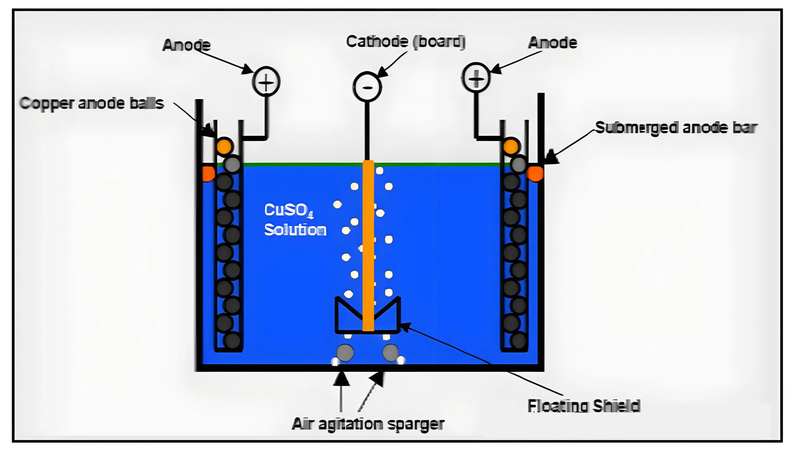
Princípio do placar de PCB
Composição e função da solução
— CuSO4
Fornece o Cu2+ necessário para o revestimento, Facilitar a transferência de íons de cobre entre ânodo e cátodo.
— H2SO4
Aprimora a condutividade da solução de revestimento.
— Cl–
Ajuda na formação do filme anódico e dissolução do ânodo, Melhorando a deposição e cristalização de cobre.
— Aditivos de revestimento
Melhore a finura da estrutura cristalina da camada e o desempenho de revestimento profundo.
A. A taxa de concentração de íons de cobre em relação ao ácido sulfúrico e ao ácido clorídrico na solução de revestimento de sulfato de cobre afeta diretamente a capacidade de revestimento profundo dos buracos e orifícios cegos.
B. O conteúdo mais alto de íons de cobre resulta em menor condutividade da solução, Ou seja,, maior resistência, que é prejudicial para a distribuição de corrente uniforme. Portanto, Para Harts, um cobre baixo, É necessário sistema de solução de alto ácido.
C. para orifícios cegos, Devido à pior circulação da solução dentro, É necessária uma maior concentração de íons de cobre para sustentar a reação.
Por isso, Produtos que apresentam Harts e buracos cegos apresentam duas direções opostas ao revestir, constituindo a dificuldade dele.
III. Projeto experimental e análise de resultados
① Informações do produto
Espessura da placa: 2.6milímetros, diâmetro mínimo do orifício: 0.25milímetros,
proporção máxima de meio-buraco: 10.4:1;
② buracos cegos
1) Espessura dielétrica 70um (1080pp), diâmetro do orifício 0,1 mm
2) Espessura dielétrica 140um (2*1080pp), diâmetro do orifício 0,2 mm
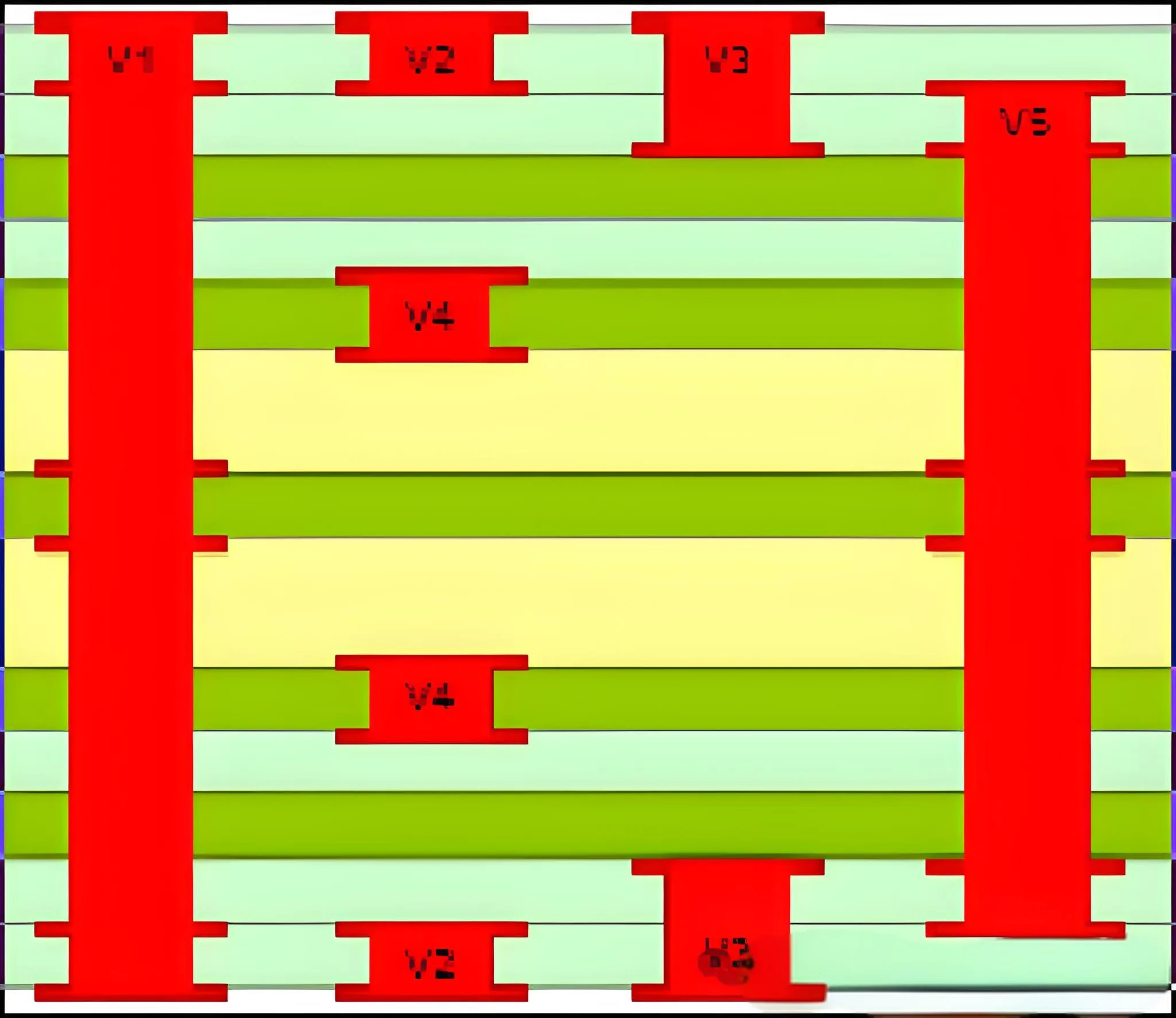
Análise de resultados experimentais de revestimento de IDH com base na proporção
③ Planos de configuração de parâmetros

Plano experimental de eletroplatação de IDH
Planeje um
Revestimento direto após deposição de cobre
Utilizar um ácido alto, proporção de solução de baixo cobre com aditivos de revestimento H; Densidade atual 10asf, Tempo de revestimento 180min.
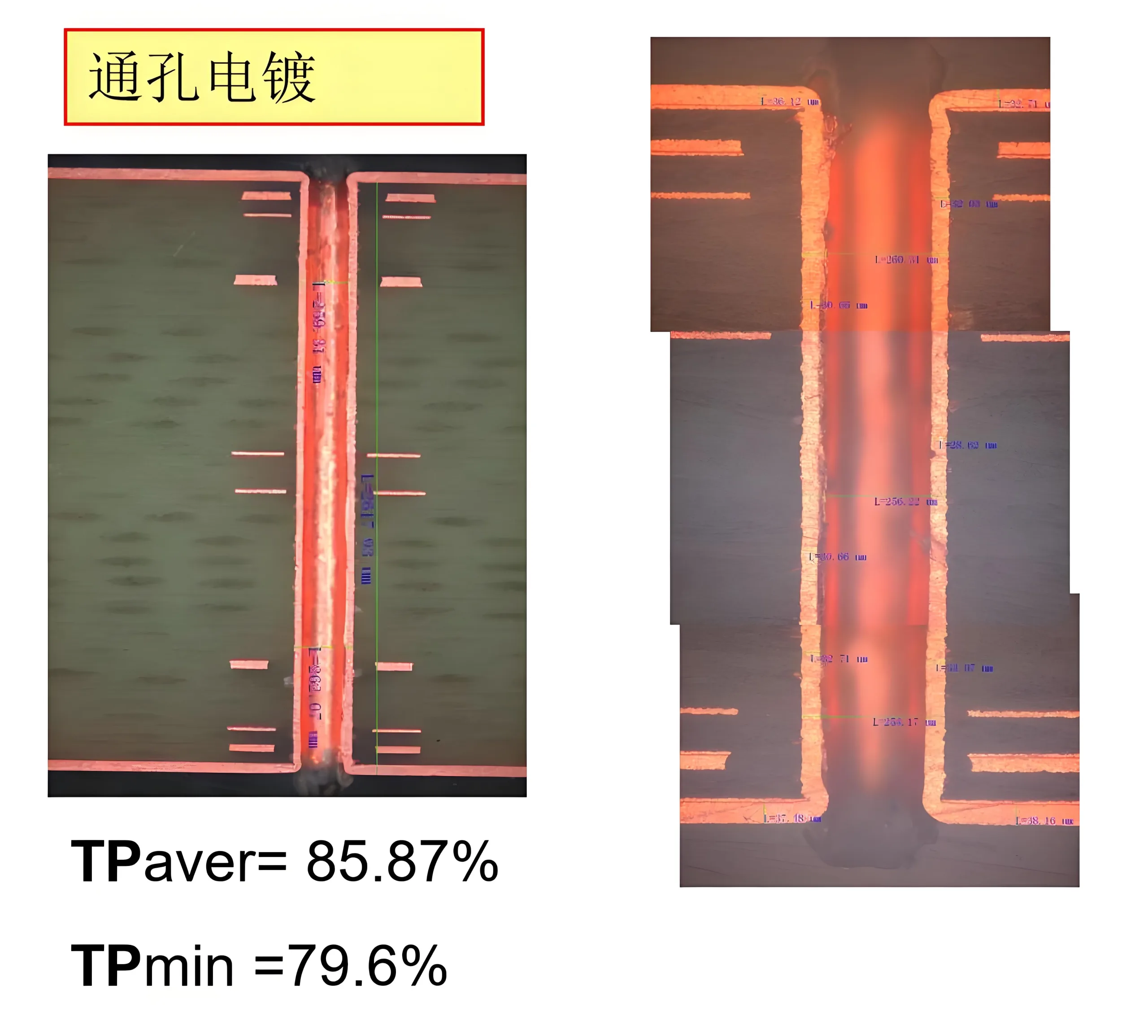
Revestimento direto após deposição de cobre
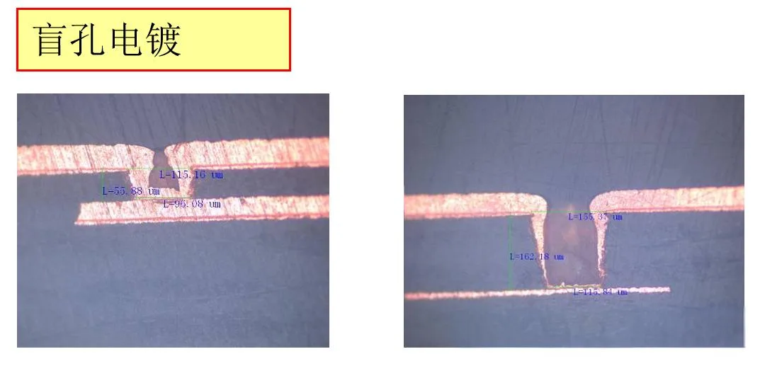
Brilho cego de IDH
1) Espessura dielétrica 70um (1080pp), diâmetro do orifício 0,1 mm: Entrada do orifício selado, Espessura do cobre inferior do orifício 14-16um
2) Espessura dielétrica 140um (2*1080pp), diâmetro do orifício 0,2 mm: BURO BOLD CARRACHEET, espessura 4-5um
— Resultados finais de teste aberto/curto
Este lote tinha um 100% Taxa de falha no teste final/curto final, com um 70% Taxa de falha especificamente no local do orifício cego de 0,2 mm (Pp 1080*2).
Plano dois
Teste usando solução de revestimento padrão para orifícios cegos, seguidos de revestimento de orifício por meio:
1) Use VCP para revestimento de orifício cego de base, Razão ácida padrão, H aditivos de revestimento, Densidade atual 15asf, Tempo de revestimento 30min
2) Use uma linha de dragão para espessamento, alto ácido, proporção de baixo cobre e aditivos de revestimento H, Densidade atual 10asf, Tempo de revestimento 150min
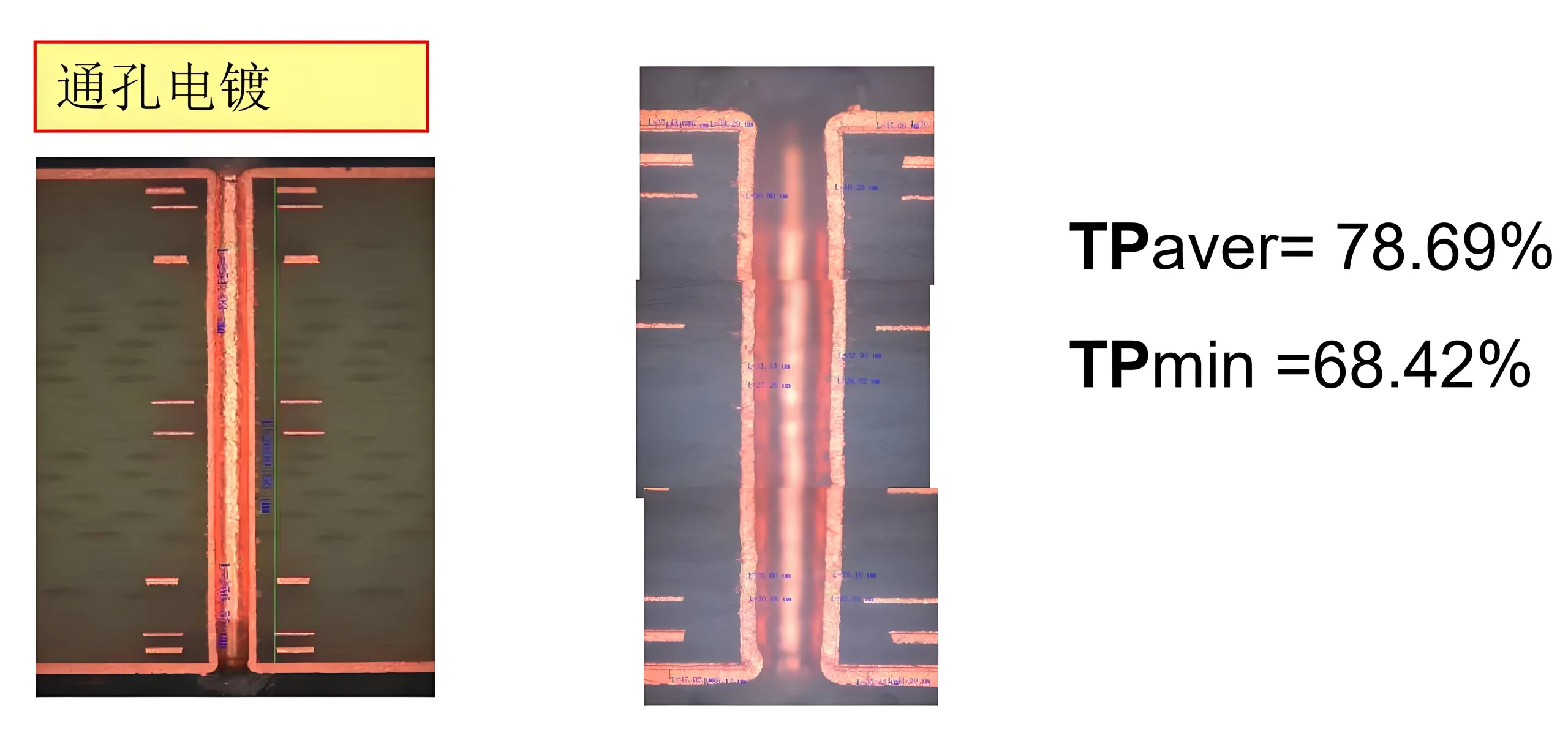
Balqueto de orifício IDH
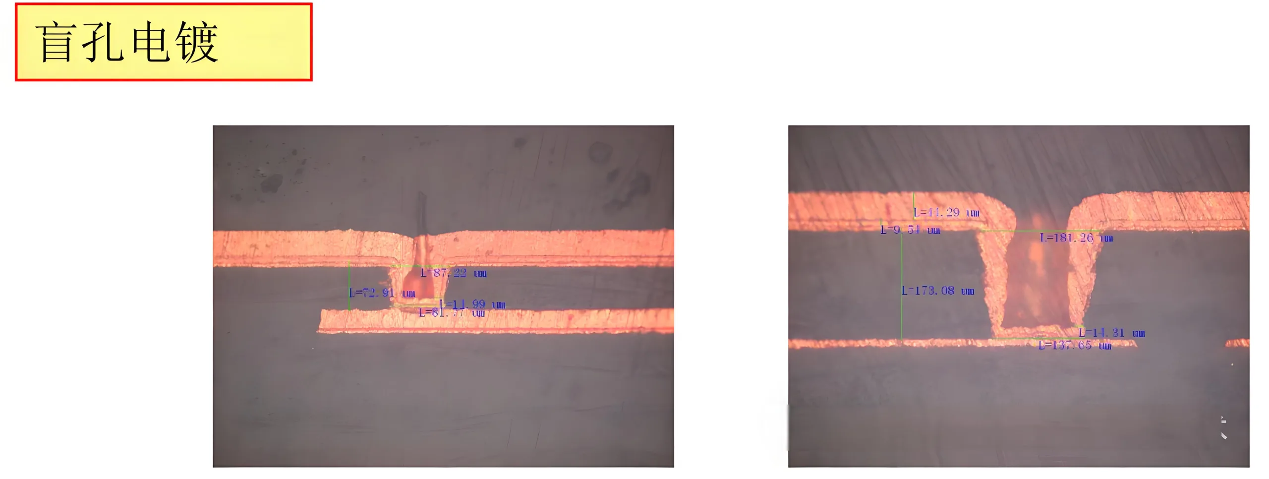
Brilho cego de IDH
1) Espessura dielétrica 70um (1080pp), diâmetro do orifício 0,1 mm: Entrada do orifício selado, Espessura do cobre inferior do orifício 14-16um
2) Espessura dielétrica 140um (2*1080pp), diâmetro do orifício 0,2 mm: BURO BOLD CARRACHEET, espessura 14-16um
— Resultados finais de teste aberto/curto
Este lote tinha um 45% Taxa de falha no teste final/curto final, com um 60% Taxa de falha especificamente no local do orifício cego de 0,2 mm (Pp 1080*2).
Comparando os dois experimentos, A questão principal estava com o revestimento do buraco cego, validando que o alto ácido, O sistema de solução de baixo cobre não é adequado para orifícios cegos.
Portanto, no experimento três, Escolhemos um ácido baixo, Solução de orifício de preenchimento de alto cobre para revestimento de orifício cego de base, enchendo o fundo dos orifícios cegos antes de prosseguir com o prato cego.
Plano três
Usando a solução de revestimento de orifício de enchimento para revestimento de orifício cego de base, seguido de revestimento de orifício por meio:
1) Use solução de revestimento de orifício de enchimento para revestimento de orifício cego de base, Razão de cobre de baixo ácido de alto cobre e aditivos de revestimento em V, Parâmetros de revestimento 8asf@30min+12@asf30min
2) Use uma linha de dragão para espessamento, proporção de alto cobre de alto ácido e aditivos de revestimento H, Parâmetros de revestimento 10asf, Tempo de revestimento 150min
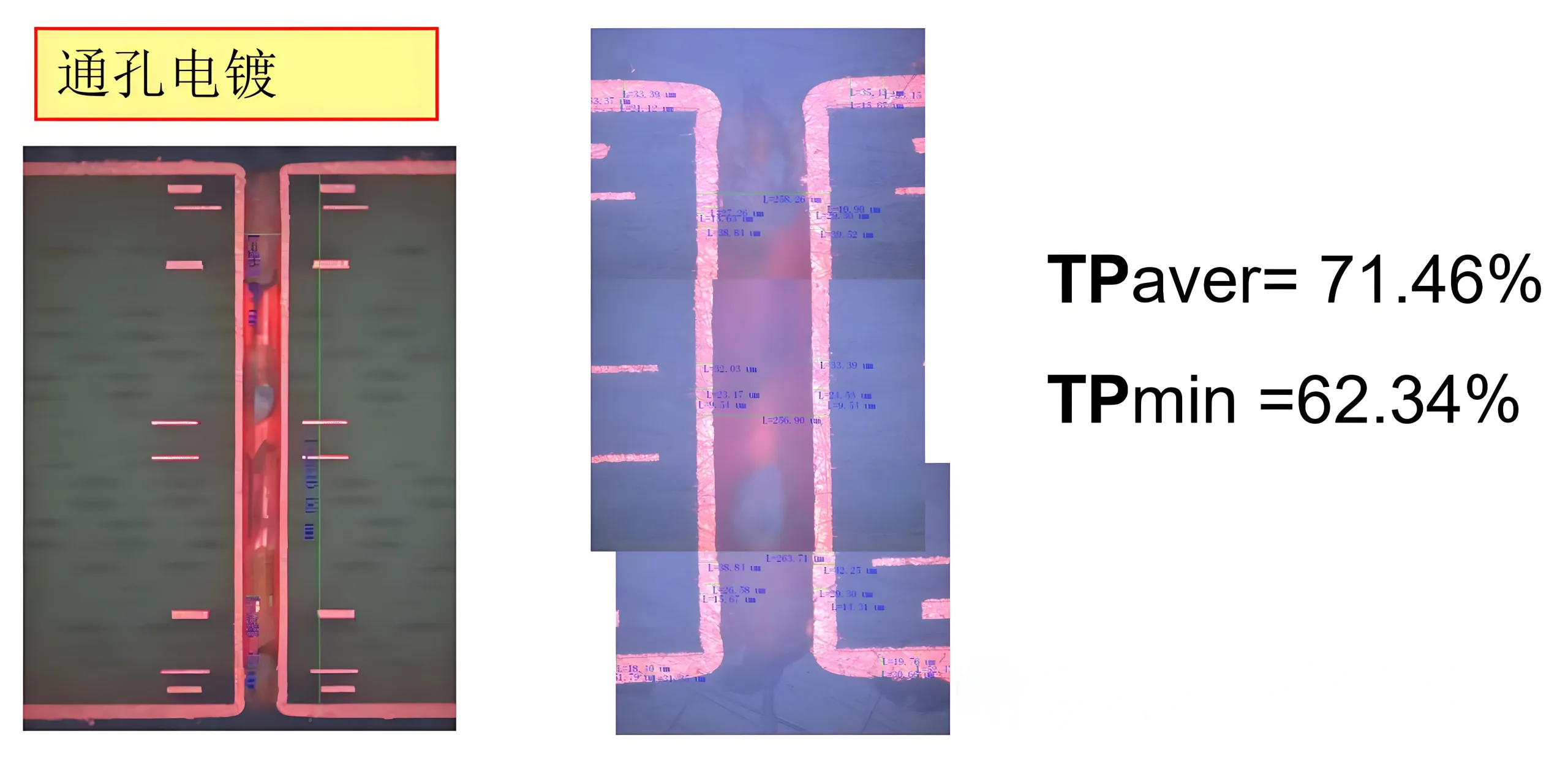
Plantar vias de orifício com uma base condutiva antes de eletroplicar

Brilho cego de IDH
1) Espessura dielétrica 70um (1080pp), diâmetro do orifício 0,1 mm: Buraco cego preenchido
2) Espessura dielétrica 140um (2*1080pp), diâmetro do orifício 0,2 mm: Espessura do buraco cego 73.63um
Projeto experimental e análise de resultados
Através da comparação experimental, Diferentes proporções de ácido-cobre e aditivos de revestimento exibem efeitos variados sobre o revestimento do orifício cego e do orifício cego. Para tábuas de IDH com altas proporções, onde os buracos cegos coexistem, É necessário encontrar um ponto de equilíbrio para resolver problemas com a espessura do cobre dentro de orifícios e caranguejos em buracos cegos. Essa espessura de cobre de superfície processada tende a ser mais espessa, frequentemente necessitando de escovação mecânica para atender aos requisitos de gravação da camada externa.
Nos testes finais de quebra de cobre, Todos os três lotes mostraram melhorias, com o primeiro e o segundo lotes tendo 100% e 45% Taxas de falha, respectivamente, Especialmente no local do orifício cego de 0,2 mm (Pp 1080*2) com taxas de falha de 70% e 60%, enquanto o terceiro lote passou completamente sem tais problemas, alcançando um 100% taxa de aprovação e demonstrando melhora significativa.
Comentários finais
Esta melhoria fornece uma solução eficaz para o processo de eletroplicação de placas HDI de alta proporção de aspecto, Mas ainda é necessário otimização de parâmetros para obter uma espessura mais fina de cobre na superfície. Espera -se que isso possa servir como uma referência valiosa para colegas, Oferecendo procedimentos de processamento abreviados e mais gerenciáveis para fabricação de placas de IDH de alta proporção.
 LOGOTIPO UGPCB

