Introduction to Battery Protection PCB
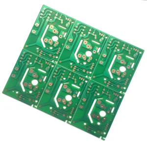
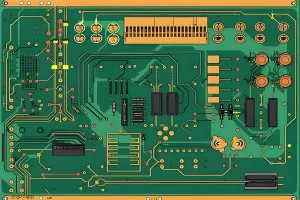
Battery protection PCB, as the name implies, is primarily designed for rechargeable batteries (typically lithium batteries) to safeguard the integrated circuit board. The necessity for lithium battery (rechargeable type) protection stems from its inherent characteristics.
Battery Protection PCB Components
The finished lithium battery comprises two parts: the lithium battery cell and the protection plate. The lithium battery cell is mainly composed of a positive plate, diaphragm, negative plate, and electrolyte. Many individuals are unaware of the role of the lithium battery protection plate. As its name suggests, the lithium battery protection plate is intended to protect the lithium battery. Its function is to safeguard the battery from discharging, charging issues, current fluctuations, and output short circuit protection.
Importance of Lithium Battery Protection
Battery protection PCB is essentially an integrated circuit board for rechargeable (commonly known as lithium battery) protection. Lithium batteries, due to their material composition, cannot tolerate overcharging, over-discharging, overcurrent, short-circuiting, and ultra-high temperature charging and discharging. Portanto, lithium battery components are always accompanied by a protection board equipped with a sampling resistor and a current fuse.
Protection Mechanisms
The protection function of lithium batteries is typically executed by the protection circuit board and current devices like PTC or TCO. The protection board, composed of electronic circuits, can accurately monitor the voltage and charge/discharge current of the cell within a temperature range of -40°C to +85°C. The loop current can instantly control the on and off of the current loop. PTC or TCO can prevent severe battery damage in high-temperature environments.
Components of the Protection Board
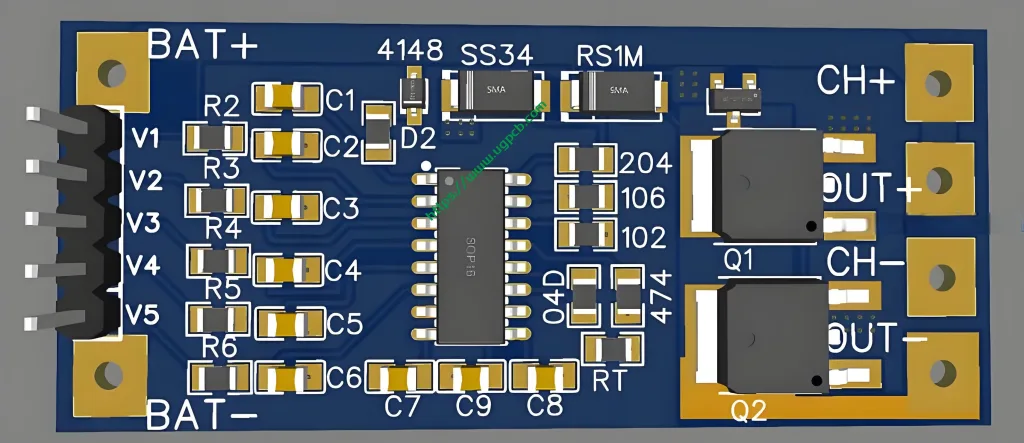
The protection board typically includes a control IC, MOS switch, precision resistor, and auxiliary devices such as NTC, ID memory, and PCB. The control IC controls the MOS switch to turn on under normal conditions, enabling the cell to communicate with the external circuit. When the cell voltage or loop current exceeds the specified value, it immediately controls the MOS switch to turn off (within tens of milliseconds) to protect battery safety.
NTC (Negative Temperature Coefficient) decreases in resistance as the ambient temperature rises, allowing electrical or charging equipment to respond promptly and control internal interruptions to stop charging and discharging. ID memory, often a single-wire interface memory, stores information such as battery type and production date, aiding in product traceability and application restrictions.
PTC (Positive Temperature Coefficient) Devices
PTC is crucial in battery assembly products, bearing a significant responsibility for battery safety. Its performance and quality are also a key factor in battery pack performance and quality. In battery products, PTC prevents high-temperature battery discharge and unsafe high currents, with special requirements based on the battery’s voltage, current density characteristics, and application environment.
Technical Considerations in Protection Board Design
When the protection board safeguards a single battery cell, the design is relatively straightforward but technically demanding. For instance, the voltage platform issue needs attention in power battery protection board design. Power batteries often require a large platform voltage during use, so the protection board design should ensure it doesn’t affect battery discharge voltage, demanding high-performance control ICs, precision resistors, and other components. Domestic ICs can meet most product requirements, while imported products may be used in special cases. Current sampling resistors must meet high precision, low temperature coefficient, and no inductance requirements, often using JEPSUN resistors. Multi-cell protection board design has higher technical requirements, with varying levels of complexity based on different needs.
Main Technical Functions of Battery Protection PCB
- Overcharge protection
- Overdischarge protection
- Overcurrent and short-circuit protection
Solutions After Mobile Phone Battery Protection Activation
- Charge the phone directly with the original charger, which will automatically activate the battery protection board’s protection circuit.
- Instantly short-circuit the battery’s positive and negative poles, observing sparks on the electrodes. Try several times before using direct charging.
- Find a 5V direct current source and lightly touch the battery’s positive and negative poles with the corresponding poles several times before charging with the original charger.
 LOGOTIPO UGPCB
