Introduction
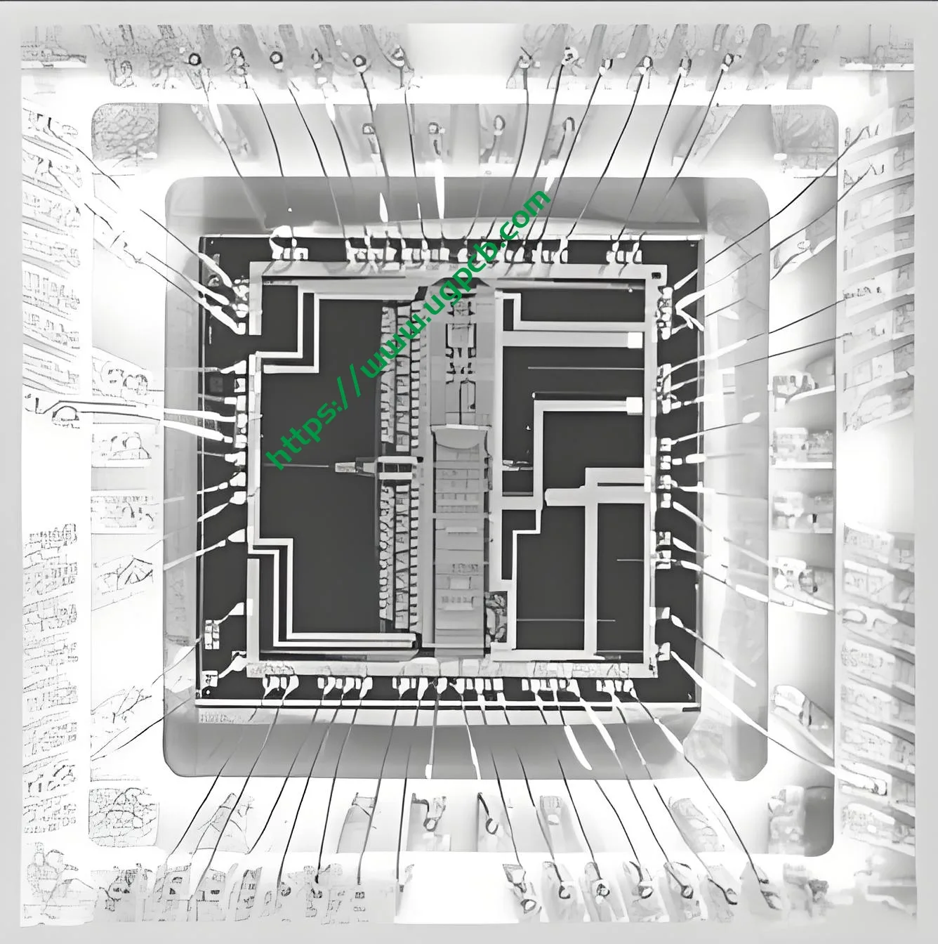
In the field of package design, especially in Wire Bonding (WB) technology, the definition of Bond Pad Opening (BPO) is a crucial step. A reasonable BPO can not only ensure the stability of the bonding process but also optimize the overall performance of the package. This article will delve into how to scientifically define the BPO size in Wire Bonding packages through theoretical analysis and practical calculations.
Background Introduction
While writing an article on Intermetallic Compounds (IMC) recently, I stumbled upon a paper discussing the relationship between wire diameter and Free Air Ball (FAB) size. The paper concluded that the optimal pairing occurs when the FAB diameter is twice the wire diameter. This finding sparked my deep thinking about defining BPO.

Initial Confusion in Defining BPO
Three years ago, when I first ventured into the field of package design, the first question I encountered was: for 25um gold wire, what should the BPO size be? Although I had years of WB experience, this reverse-engineering question still posed a challenge.
Optimal FAB and Ball Diameter Relationship
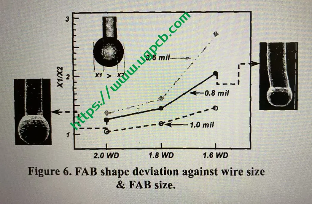
To answer this question, let’s first explore the relationship between the optimal FAB and ball diameter. Below is a chart sent to me by a friend who specializes in WB, illustrating the relationship between FAB ball diameter and off-center balls:
<img src=”https://example.com/fab-off-center-ball-chart.png” />
From the chart, we can draw the following conclusions:
- The optimal FAB is twice the wire diameter (WD), i.e., X1:X2 approaches 1:1.
- Smaller wire diameters are more prone to off-center balls.
- A ball with an X1:X2 ratio greater than 2:1 is considered an off-center ball. Prin urmare, when the wire diameter is greater than 0.8mil, the ball diameter is recommended to be between 1.6WD and 2.0WD. When the wire diameter drops to 0.6mil, this range narrows to 1.7WD to 2.0WD.
SPT Formula and Parameter Analysis
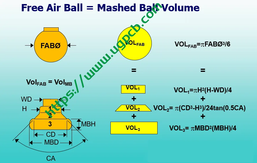
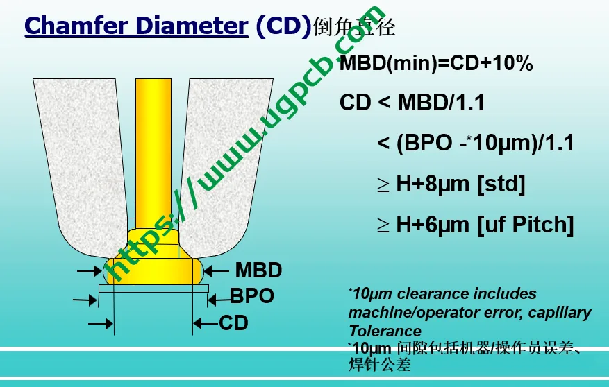
With the optimal ball diameter range established, we can calculate the optimal Ball Size using a formula provided by SPT (a renowned semiconductor packaging equipment supplier). The formula introduces multiple wedge parameters, including H (wedge height), CD (wedge diameter), CA (wedge angle), MBD (ball diameter), and MBH (ball thickness).
Optimal Parameter Reference Values
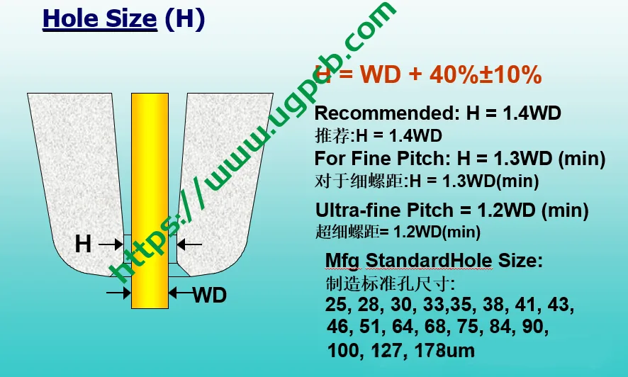
H: The optimal value is 1.4 times the wire diameter, with a minimum of 1.2 times. Too small can cause difficulties in wire feeding during looping, while too large can cause instability in looping. Prin urmare, for products with dense wire arcs, H is often taken as 1.2WD or 1.3WD.
CD: In WB processes, FAB equals CD. This size matching allows the CD’s bevel to grip the FAB more securely during bonding, preventing ball slippage and resulting anomalies.
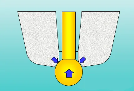
CA: Primarily functions to grip the FAB ball and influences ball shaping and energy output at the process end. Common CAs include 70°, 90°, and 120°, with 90° being the most conventional, 70° for small balls, and 120° for large balls.
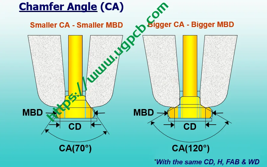
MBD and MBH: ball diameter and ball thickness. The empirical formula MBH/MBD=0.18~0.3, usually 0.25 is taken as the reference value. At this ratio, it is easy to get a relatively flat bottom surface of the ball, which is more important for improving cracks and obtaining uniform IMC.
Example calculation of BPO size
Below we take the 20um wire diameter as an example to calculate its recommended BPO value.
Define FAB size
Select the FAB size within the range of 1.6WD~2.0WD. If the chip has sufficient reserved area, directly select 2.0WD; if you want to get the best cost-effectiveness, you can take the middle value 1.8WD. At this time, X1:X2 is about 1.5, which is easier to implement process debugging. Let’s take 1.8WD as an example, that is, FAB is 36um.
Calculate CD
FAB=CD+1um is usually taken, taking into account the tolerance of the equipment ball size. Prin urmare, CD is taken as 35um.
Determine other parameters
H: Take 1.4WD, that is, 28um.
CA: Take the most common 90°.
MBH/MBD: Take 0.25.
Calculate MBD and extruded aluminum size
According to the above formula, it can be calculated that MBD is approximately equal to 44um. Regarding extruded aluminum, if there is no processing experience, the extruded aluminum size can be defined as the Ball Size plus 2~3um on each side. Here we directly take 3um.
Consider equipment tolerance
Equipment tolerance mainly refers to the welding accuracy of X/Y, which combines the accuracy of the workbench motor of the equipment itself, the lens recognition accuracy, and the shaking of the product during processing. The accuracy of the mainstream WB equipment on the market is now marked as ±2um~±2.5um, so we directly take the larger one.
Calculate BPO size
Finally, the best BPO size suitable for the 20um wire is 55um.
Precautions and summary
The difference between gold wire and copper wire: Gold wire and copper wire have huge differences in aluminum extrusion debugging and welding difficulty debugging. The parameters taken in this article are all intermediate values, and are based on the fact that the processing knowledge of their own products is 0. If you encounter practical problems, you can select splitters with different parameters for process debugging.
Limitations of design rules of packaging factories: The design rules provided by packaging factories are usually marked to the limit of their process capabilities. Prin urmare, risks must be carefully assessed when using them.
Well-reasoned and well-founded solutions are implemented: When a solution is implemented, it must be well-founded and the subsequent risks must be evaluated and judged. In this way, even if unexpected external factors occur, the team can accept them.
 LOGO UGPCB

