
1. Product Overview and Market Outlook for Rigid-Flex PCB
А жестко-гибкая печатная плата combines the mechanical stability of a rigid circuit board with the spatial flexibility of a flexible circuit board. This innovation creates a single board with strong support zones and bendable interconnection zones.
According to DIResearch, the global rigid-flex PCB market reached approximately 2.604 миллиард в 2025. It is projected to grow to 3.726 миллиард за 2032, с совокупным годовым темпом роста (Кагр) из 5.25%. QYResearch also reports a 2025 market size of about 2.462 миллиард, с 2032 forecast of 3.471 миллиард. Both reports clearly point to a key trend: rigid-flex PCB is one of the fastest-growing segments in the печатная плата industry today.
In 5G communication modules, носимые устройства, medical endoscopes, и аэрокосмические приложения, UGPCB’s Module Rigid-Flex Circuit Board has become the preferred solution for engineers pursuing smaller, легче, and more reliable designs.
2. Определение продукта и научная классификация
2.1 Определение продукта
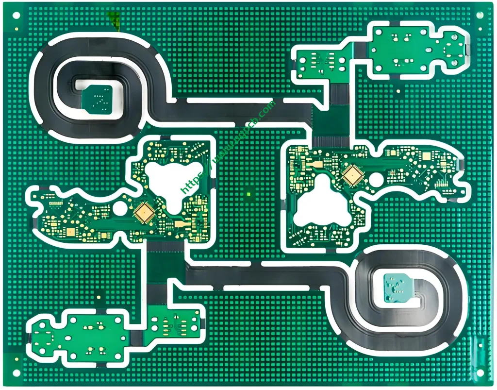
The UGPCB Module Rigid-Flex PCB uses a rigid-flex-rigid alternating stackup structure. The rigid sections provide a stable platform for mounting components. The flexible sections enable 3D bending interconnections. This design greatly reduces the number of connectors and cables needed in traditional rigid PCB systems, which significantly improves system reliability and space efficiency.
2.2 Научная классификация
According to IPC-6013D, the specification for qualification and performance of flexible and rigid-flex printed boards, UGPCB’s product belongs to the Rigid-Flex Multilayer category. This is one of the highest-level constructions in flexible printed boards, comparable with single-sided, двусторонний, and multilayer flexible boards. The product uses an FR4 + PI composite material system and a symmetrical 4-layer rigid plus 2-layer flexible stackup. It is a typical 6-layer rigid-flex board with a 4R+2F structure, including plated through holes (ПТХ) and blind/buried vias.
This product complies with IPC-6013E (2021 edition) requirements for rigid-to-flex transition zones. These requirements cover marking, annular rings, copper-filled microvias, and selective hole plating. Примечательно, IPC-6013E also sets strict rules for surface mount pad anomalies, inner-layer plated hole wall dielectric removal, and lead and etch back.
3. Key Design Parameters and Technical Specifications
| Параметр | Спецификация | Описание |
|---|---|---|
| Строительство | FR4 4-layer + PI 2-layer | 4R+2F symmetrical stackup |
| Total Finished Thickness | 0.70мм (0.15mm flex + 0.55mm rigid) | Precisely matched for module packaging thickness requirements |
| Толщина готовой меди | 1унция / 1унция / 1унция / 1унция / 1унция / 1унция | 35μm per layer ensures uniform current carrying capacity |
| Минимальная трассировка / Космос | 4мил / 4мил (0.10мм / 0.10мм) | Meets medium-density routing requirements |
| Поверхностная отделка | СОГЛАШАТЬСЯ | Nickel layer 3–5μm, gold layer 0.03–0.1μm |
| Спорная маска цвет | Зеленый / Белый | Supports visual identification for different applications |
4. Working Principle of Rigid-Flex PCB
4.1 Basic Working Principle
The УГКПБ Module Rigid-Flex PCB works through a three-step technical path: layer-by-layer fabrication, synchronous lamination, and zone-specific conduction. Первый, а 4 rigid FR4 layers and 2 flexible PI layers undergo inner-layer circuit formation. Затем, a high-temperature, high-pressure vacuum lamination process precisely bonds them into a complete multilayer structure. PTH and multi-step blind/buried vias provide electrical interconnection between layers.
4.2 Signal Integrity in the Rigid-to-Flex Transition Zone
The rigid-to-flex transition zone is the technical core of a rigid-flex board. UGPCB follows IPC-2221 and IPC-2223 design guidelines in this zone’s manufacturing process. The company uses a stepped, gradual rigid transition design to prevent stress concentration at the bend corner. Controlling the flow and resin bleed of low-flow or no-flow prepreg ensures dielectric uniformity in the transition zone.
From a signal transmission perspective, the Z-axis coefficient of thermal expansion (Z-ось Cte) is a key indicator for evaluating hole wall reliability and preventing via cracks after thermal cycling. According to IPC-TM-650 2.4.24, the polyimide material system used in this project has a Z-axis CTE of only 1.20% in the 50–260°C range. This is significantly lower than the 3%–4% of standard FR4 (источник: SH260 technical data sheet, Shengyi Technology). This means UGPCB’s module board maintains mechanical integrity in plated through holes after multiple reflow soldering thermal cycles.
5. Main Applications and Use Scenarios
5.1 Key Advantages in Module-Based Electronics
The UGPCB Module Rigid-Flex PCB is specifically designed for module packaging. It provides several key benefits in RF modules, power management modules, and sensor modules:
-
Replaces connectors and cables: Rigid areas carry components while flexible areas directly serve as interconnection cables. This eliminates insertion loss and contact failure risks from traditional board-to-board connectors. In high-frequency signal transmission, this reduces impedance discontinuities to a minimum.
-
Simplifies assembly: One rigid-flex board does the job of a rigid PCB, a flexible cable, и разъемы. This can simplify the BOM by 30% к 50%.
-
Reduces weight and size: In weight-limited applications like drone flight control modules and satellite payload modules, using a rigid-flex board can lower the final product’s weight by more than 40% compared with traditional solutions.
5.2 Representative Applications
Based on its structural features and technical specifications, this product fits the following typical scenarios:
| Поле приложения | Specific Products | Reasons for Selection |
|---|---|---|
| Бытовая электроника | Smartphone camera modules, foldable phone hinge PCBs, TWS earbud charging modules | Replaces flex cable + ФПК + Разъем БТБ, improves bending life |
| Промышленный контроль | Robotic joint driver modules, PLC control card modules, servo drive modules | FR4 rigid areas resist vibration, PI flex adapts to compact wiring |
| Медицинские устройства | Endoscope image capture modules, portable ultrasound probe modules, implantable neurostimulator modules | ENIG surface finish resists corrosion, material system meets biocompatibility pretreatment |
| Аэрокосмическая промышленность | Satellite onboard computer modules, telemetry modules, Z-fold interconnections | PI flex material maintains electrical stability from -55°C to +125°C |

6. Material Selection and Performance Analysis
6.1 ФР4 + PI Composite Material System
| Area | Base Material Type | Key Material Properties |
|---|---|---|
| Жесткая зона | ФР-4 (glass fabric reinforced epoxy resin copper-clad laminate) | UL94 В-0 flame retardant rating, high mechanical strength, mature supply chain |
| Flex Area | Polyimide Film | Тг >250°С, Тд >405°С (5% mass loss), Z-axis expansion rate only 1.20% |
Полиимид (ПИ) is the gold standard base material for flexible areas primarily because of its excellent thermal stability. Its glass transition temperature Tg exceeds 250°C, which allows it to withstand lead-free reflow soldering with a peak temperature of 260°C without significant softening. Также, PI’s CTE is approximately 2–3×10⁻⁵/°C, which closely matches copper’s CTE of about 1.7×10⁻⁵/°C in the 100–200°C range. This reduces peel stress between the copper foil and the dielectric layer after thermal cycling.
For the rigid area, UGPCB uses FR4 that meets the UL 94 В-0 flame retardant rating. UL94 В-0 is one of the most stringent vertical burn test grades in the world. A sample must self-extinguish within 10 seconds after each of two 10-second flame applications, and no flaming drips may ignite the cotton indicator below.

6.2 Performance Advantages of ENIG Surface Finish
UGPCB’s Module Rigid-Flex PCB uses ENIG (Химическое никель, иммерсионное золото) as the surface finish. ENIG is one of the best surface finish options for high-density interconnect and high-frequency modules. Its key parameters are:
-
Base layer: electroless nickel layer (Ni–P alloy) : Typical thickness 3–5μm with 7%–9% phosphorus content. It provides supporting hardness and prevents interdiffusion between copper and gold.
-
Top layer: immersion gold layer (Au) : Thickness only 0.03–0.1μm (30–100nm). The gold layer is very dense and provides excellent wettability and an oxygen barrier for the soldering surface.
Key advantages of ENIG include:
-
Excellent surface flatness: The nickel layer fills microscopic unevenness on copper traces, creating perfectly coplanar pads for high-density pin devices like BGAs and CSPs.
-
Great oxidation and corrosion resistance: The inert gold layer maintains solderability during long-term storage for up to 12 months under standard conditions.
-
Совместимость без свинца: The nickel layer effectively prevents the formation of brittle Au–Sn intermetallic compounds between gold and solder, ensuring long-term solder joint reliability.
7. Core Manufacturing Process and Quality Control
Rigid-flex board manufacturing involves more than 35 production steps. UGPCB uses a full-process quality traceability system to ensure every rigid-flex board is genuine. Key process steps include:
7.1 Inner Layer Pattern Transfer
Each rigid FR4 layer and the two flexible PI layers separately undergo inner-layer pattern exposure using Лазерная прямая визуализация (LDI). After dry film lamination, high-energy UV light sources directly expose the image. This avoids the film distortion and dimensional variation associated with traditional film exposure, ensuring good yield for 4mil/4mil trace width, consistently above 95%.
7.2 Stackup and Vacuum Lamination
Low-flow or no-flow prepreg bonds the rigid and flexible areas. UGPCB uses vacuum lamination equipment with stepped temperature rise and precise pressure control. This achieves complete air removal and bubble-free resin filling in the rigid-to-flex transition zone, preventing uneven thickness or delamination failures.
7.3 Drilling and Hole Metallization
In this rigid-plus-flex multilayer structure, механическое бурение (bit diameter ≥0.15mm) handles the rigid FR4 areas. CO₂ or UV laser drilling handles the flexible PI or coverlay areas to achieve microvias as small as 0.075mm. Desmear and hole wall metallization for the stackup material strictly follow IPC-TM-650 standards.
7.4 ENIG Surface Finish
After the outer layer solder mask and legend printing, the whole board goes through the ENIG electroless nickel and immersion gold process sections. A computer with real-time PID closed-loop control monitors the bath temperature, pH level, and nickel-phosphorus ratio. This ensures uniform nickel thickness and gold coverage from the board edge to the center.
7.5 Coverlay Removal and Profiling
At the boundary between rigid and flexible areas, this product needs to remove unnecessary FR4 waste during final cutting. UGPCB uses a combined process of pre-routing plus laser precision depth trimming, controlling cutting depth error within ≤±0.05mm (источник: UGPCB SOW processing control table). Затем, operators gently tear along the pre-cut V-groove to detach excess board material. This completely avoids delamination and microcracks caused by high-speed routing.
8. Design Guidelines and DFM Recommendations
To ensure high-yield mass production and signal integrity for a module rigid-flex PCB, pay close attention to these design guidelines:
-
Bend zone routing and stackup: Do not place any plated through holes (ПТХ) or test points in the flexible bend zone. Doing so could cause main circuit disconnection from cracks in drilled holes or plated copper when bending. Keep trace counts low in the bend zone and use smooth transitions. Avoid 90-degree angle bends.
-
Registration accuracy in rigid-to-flex transition zone: According to IPC-6013D, strictly control the relative shift of annular rings between the rigid and flexible sections. This ensures copper vias do not expose bare dielectric fibers at the PI interface in the rigid zone. UGPCB’s engineering control keeps layer-to-layer misalignment below 50μm.
-
Impedance control and stackup: In high-frequency module designs, consider the dielectric interface between PI material (DK ~3.4 at 1GHz) and FR4. Avoid impedance discontinuities in the transition zone. UGPCB factory verification shows that with 4mil trace width/spacing, differential impedance can be stably controlled within 100Ω ± 5%.
9. Product Features and Competitive Advantages
-
Lightest and thinnest: Total finished thickness is only 0.70mm (rigid area 0.55mm, flexible area 0.15mm). Minimum bend radius can be as low as 10 times the board thickness (approximately 1.5mm).
-
Heat-resistant and stable: Uses a polyimide system with Tg >250°С, easily withstanding 260°C peak lead-free reflow soldering without significant delamination or softening.
-
Надежный: Plated copper in multilayer blind/buried vias and full-board PTH eliminates contact impedance from cables and connectors in the original design. UGPCB’s finished board can withstand random vibration up to 60G (Grms standard) and passes IPC Class 3 тестирование.
-
Space-saving: The 4R+2F 6-layer construction fits easily within a 3mm gap in foldable electronic devices. It replaces the space needed for two rigid boards, one cable, and four board-to-board connectors.
10. Summary: Why Choose UGPCB’s Module Rigid-Flex PCB?
UGPCB’s rigid-flex board combines rigid strength and flexible adaptability perfectly for module packaging, thanks to professional electronic design capabilities and precise manufacturing execution. With FR4+PI materials, it achieves a 0.70mm ultra-thin 3D interconnection. The ENIG surface finish ensures high-fidelity signal transmission and soldering reliability. Compared with traditional rigid board plus connector solutions, UGPCB’s Module Rigid-Flex PCB offers the best overall value in cost, космос, масса, и надежность.
Want to simplify your supply chain and improve product reliability with modular design?
📩 Get a Quote and Sample Today!
-
📧 Email your PCB Gerber files and technical requirements to sales@ugpcb.com
-
🌐 Visit www.ugpcb.com to receive a 24-hour quote response
-
📞 Call our technical sales engineer for a professional DFM review report (IGES 3D modeling form analysis)
УГКПБ: Your global partner for rigid-flex PCB modules, adding a folding dimension to your designs.


