You must have seen various interfaces on many electronic device circuit boards, such as GPIO, ไอทูซี, เอสพีไอ, ยูอาร์ที, ใช้, USB, ฯลฯ. You must be curious about the working principles, purposes, and differences between these interfaces on the circuit boards. Today, our editor visited colleagues from the technical department of UGPCB company to explain their “true nature.”
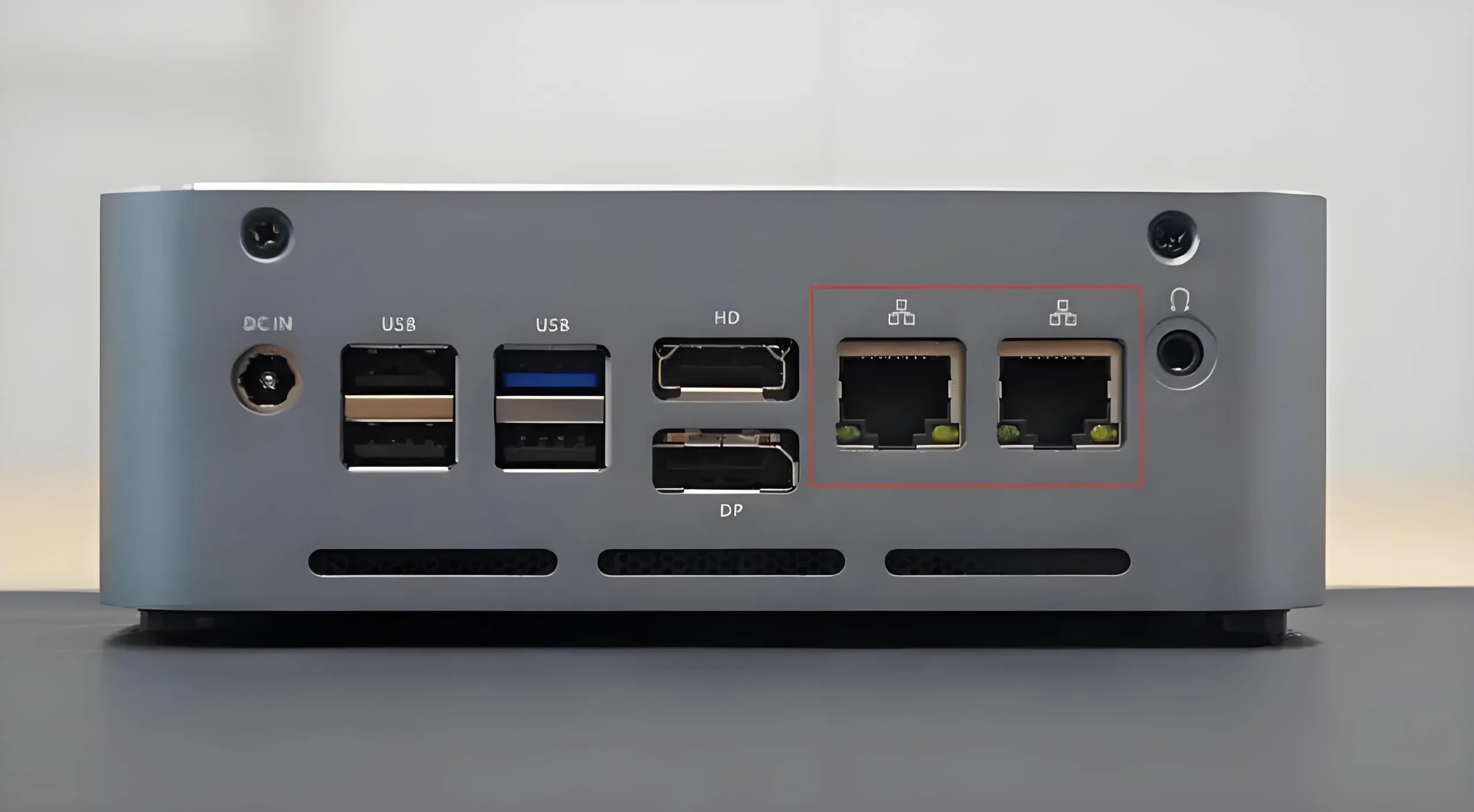
Communication Interfaces
Simple Differences
1) GPIO (General Purpose Input Output) is a general-purpose input/output, general port, bus extender that simplifies I/O expansion using industrial standard I2C, SMBus™, or SPI™ interfaces. When microcontrollers or chipsets lack enough I/O ports, or when systems require remote serial communication or control, GPIO products can provide additional control and monitoring functions.
2) เอสพีไอ (Serial Peripheral Interface) is a standard four-wire synchronous bidirectional serial bus. The SPI interface is mainly used in EEPROM, FLASH, real-time clocks, AD converters, and between digital signal processors and digital signal decoders. SPI is a high-speed, full-duplex, synchronous communication bus that occupies only four pins on the chip, saving pin counts and PCB layout space. Due to its simple and easy-to-use characteristics, more and more chips are integrating this communication protocol.
3) ฉัน2C (INTER-IC BUS) is a two-wire serial bus developed by PHILIPS for connecting microcontrollers and their peripheral devices. It is a widely adopted bus standard in the field of microelectronic communication control. It has the advantages of fewer interface lines, simple control methods, small device packaging forms, and higher communication rates.
4) ยูอาร์ที (Universal Asynchronous Receiver Transmitter) is a universal asynchronous receiver/transmitter device.
5) USART Universal Synchronous Asynchronous Receiver Transmitter;
6) USB Universal Serial Bus (Universal Serial Bus)
7) CAN Fieldbus
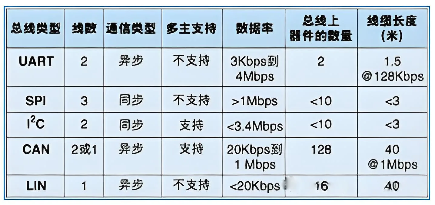
Table of Interface Transmission Parameters
Composition of Transmission Data Lines
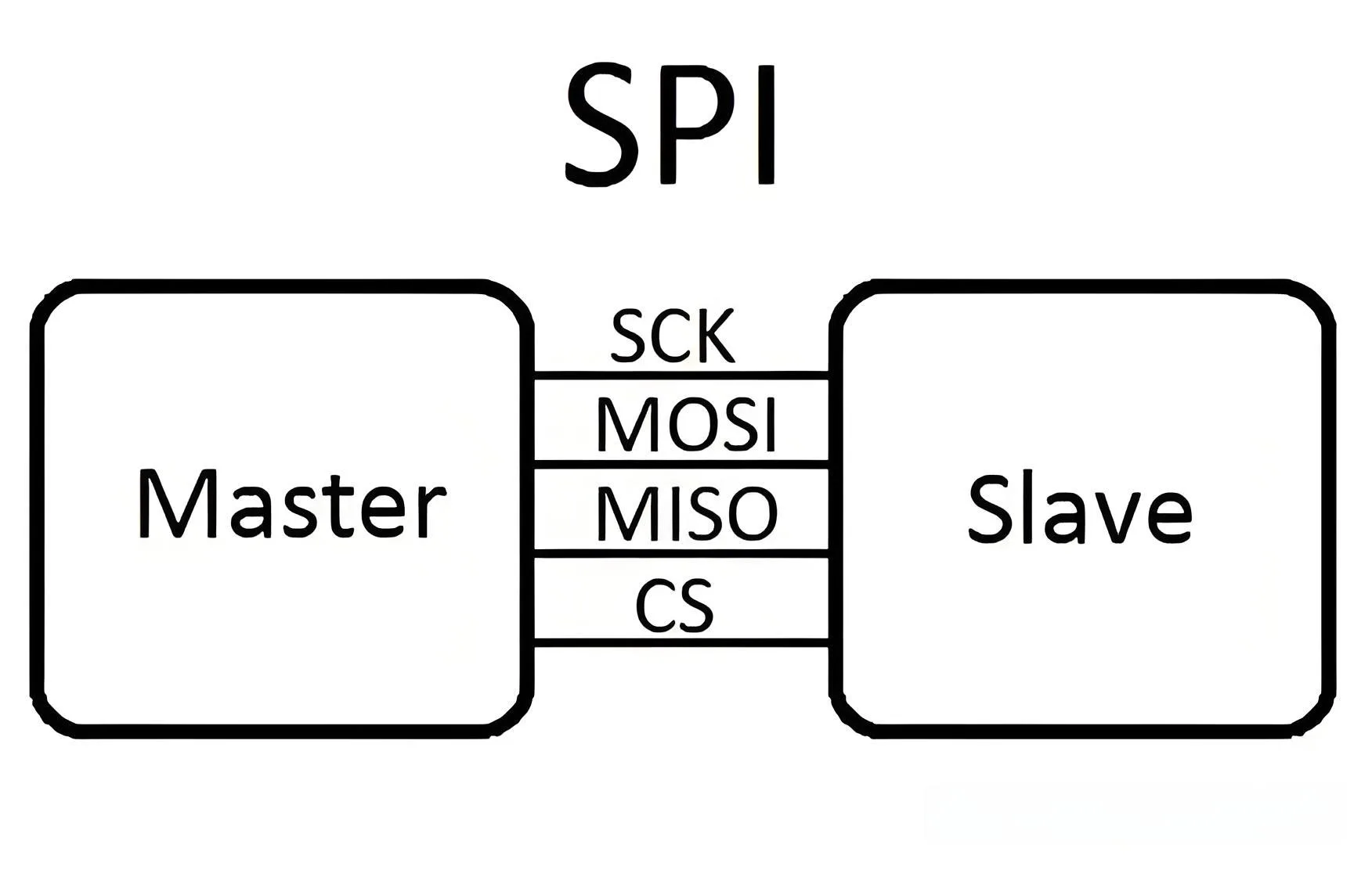
The SPI bus consists of three signal lines Serial Clock (SCLK), Serial Data Output (SDO), and Serial Data Input (SDI). The SPI bus can connect multiple SPI devices. The SPI device providing the SPI clock is the master or main device (Master), while other devices are slaves or slave devices (Slave). Master and slave devices can achieve full-duplex communication. When there are multiple slave devices, an additional slave select line can be added.
If simulating the SPI bus with general IO ports, it is necessary to have one output port (SDO), one input port (SDI), and depending on the type of device implemented, another port if implementing master and slave devices, requiring both input and output ports; if only implementing master devices, an output port is sufficient; if only implementing slave devices, an input port is needed.
The I2C bus is a two-way, two-wire (SCL, SDA), serial, multi-master interface standard with a bus arbitration mechanism, making it very suitable for close-range, infrequent data communications between devices. In its protocol system, when transmitting data, the destination device’s address is included, enabling device networking.
If simulating the I2C bus with general IO ports for bidirectional transmission, one input/output port (SDA) is needed, and another output port (SCL) is required. (Note My understanding of I2C is relatively limited, so this description may be incomplete.)
The UART bus is an asynchronous serial port, so it generally has a much more complex structure than the previous two synchronous serial ports (as introduced in microcontroller books, though it’s not considered complex). It generally consists of a baud rate generator (the generated baud rate is equal to 16 times the transmission baud rate), a UART receiver, and a UART transmitter, with two wires in hardware, one for sending and one for receiving.
Clearly, if simulating the UART bus with general IO ports, one input port and one output port are required.
From the second point, it is apparent that SPI and UART can achieve full duplex, but I2C cannot.
Communication Protocol Differences
เอสพีไอ
เอสพีไอ
SPI is a protocol that allows a master device to initiate synchronous communication with a slave device, thereby completing data exchange. This communication method has the advantage of occupying fewer ports; โดยทั่วไป, four are enough for basic communication. ในเวลาเดียวกัน, the transmission speed is also very high. โดยทั่วไป, it requires the master device to have an SPI controller (but it can also be simulated) to communicate with SPI-based chips.
The communication principle of SPI is very simple; it requires at least four wires, but three can also suffice. They are common to all SPI-based devices SDI (data input), SDO (data output), SCK (clock), CS (chip select). The CS controls whether the chip is selected, meaning operations on this chip are only effective when the chip select signal is at a predetermined enable signal (high level or low level). This allows multiple SPI devices to be connected on the same bus.
Next are the three lines responsible for communication. Communication is completed through data exchange. Here, it’s important to know that SPI is a serial communication protocol, meaning data is transmitted bit by bit. This is why the SCK clock line exists. The SCK provides clock pulses, and SDI, SDO complete data transmission based on these pulses. Data output occurs through the SDO line; data changes on the rising edge or falling edge of the clock and is read at the immediate following falling or rising edge. One bit of data transmission is completed in this way. Input follows the same principle. Thus, at least eight changes in the clock signal (one up and down cycle constitutes one change) allow for the transmission of 8 bits of data.
It should be noted that the SCK signal line is controlled only by the master device, and slave devices cannot control the signal line. ในทำนองเดียวกัน, in an SPI-based device, there must be at least one master device.
This transmission characteristic has an advantage over typical serial communications unlike conventional serial communication, which transmits at least 8 bits of data continuously, SPI allows data to be transmitted bit by bit, and even permits pausing because the SCK clock line is controlled by the master device. When there is no clock transition, the slave device does not collect or transmit data. In other words, the master device can control the communication through control of the SCK clock line.
SPI is also a data exchange protocol since the SPI data input and output lines are independent, they allow simultaneous completion of data input and output.
Different SPI devices have different implementations, mainly in terms of when data changes and is collected, with different definitions for collection on the rising edge or falling edge of the clock signal. For specific details, please refer to the documentation of the relevant devices.
ฉัน2C
Only two bus lines are required one serial data line SDA and one serial clock line SCL.
Every device connected to the bus can be addressed with a unique address and a simple master-slave relationship set by software. The host can act as a master transmitter or receiver.
It is a true multi-master bus; if two or more masters simultaneously initiate data transfer, conflict detection and arbitration prevent data corruption.
Serial 8-bit bidirectional data transfer rates can reach up to 100kbit/s in standard mode, 400kbit/s in fast mode, and 3.4Mbit/s in high-speed mode.
On-chip filters remove glitches from the bus data line to ensure data integrity.
The number of ICs connected to the same bus is limited only by the maximum bus capacitance of 400pF.
ยูอาร์ที
The UART bus is an asynchronous serial port, so its structure is generally much more complex than the previous two synchronous serial ports. It typically consists of a baud rate generator (which generates a baud rate equal to 16 times the transmission baud rate), a UART receiver, and a UART transmitter, with two wires in hardware, one for sending and one for receiving.
UART is commonly used for controlling computer chips for serial devices. One point to note is that it provides an RS-232C data terminal equipment interface, allowing computers to communicate with modems or other serial devices using the RS-232C interface.
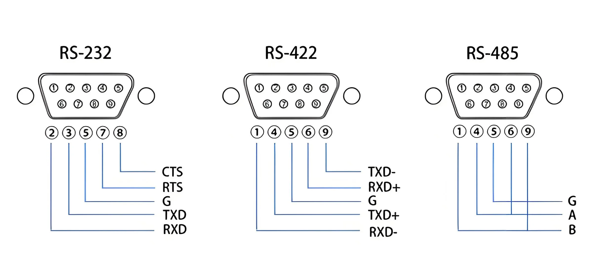
UART stands for Universal Asynchronous Receiver/Transmitter (asynchronous serial communication port). It includes standards and specifications for interfaces such as RS232, RS499, RS423, RS422, and RS485, making UART a general term for asynchronous serial communication ports. RS232, RS499, RS423, RS422, and RS485 are interface standards and specifications for various asynchronous serial communication ports, defining electrical characteristics, transmission rates, connection characteristics, and mechanical properties of the interfaces. They belong to the physical layer (the lowest layer) concept in the communication network and are not directly related to communication protocols. Communication protocols belong to the data link layer (the next higher layer) concept in the communication network. The COM port is an abbreviation for the asynchronous serial communication port on a PC (personal computer). Due to historical reasons, IBM’s PC external interface was configured as RS232, becoming the de facto standard in the PC industry. Thus, the COM ports on modern PCs are all RS232. If multiple asynchronous serial communication ports are available, they are named COM1, COM2, ฯลฯ.
It is clear that both SPI and UART can achieve full-duplex communication, but I2C cannot.
USART Universal Synchronous Asynchronous Receiver and Transmitter. (The difference from UART is evident.)
UART Universal Asynchronous Receiver and Transmitter;
USART Universal Synchronous Asynchronous Receiver and Transmitter. โดยทั่วไป, in microcontrollers, interfaces named UART are used only for asynchronous serial communication, while those named USART can be used for both synchronous and asynchronous serial communication.
USB
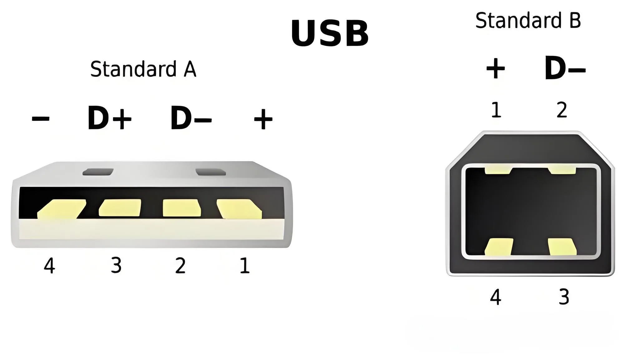
USB stands for Universal Serial Bus, an external bus standard for connecting and communicating between a computer and external devices, applied in the PC domain. USB supports the plug-and-play and hot-swap functions. USB was proposed by a coalition including Intel, Compaq, IBM, and Microsoft at the end of 1994.
USB
USB’s electrical characteristics and transmission characteristics include high-speed USB transceivers like Philips’ 82C251, TI’s SN65/75LBC031, Bosch’s CF150, C250, and Intersil’s UC5350; low-speed USB transceivers include Philips 82C252, TJA1053, Siemens TLE 6252G; single-wire USB transceivers include Philips AU5790, Infineon TLE 6255, Delphi DK166153.
CAN
When the bus is idle, any CAN node can start data transmission. If two or more nodes begin transmission simultaneously, identifier-based bit-by-bit arbitration resolves access conflicts. CAN is a broadcast-type bus where all nodes receive data from the bus, and a hardware filtering mechanism determines whether the message is provided to the node.
There are four types of message frames Data Frame, remote frame, error frame, and overload frame.
Basic CAN controllers are cost-effective with limited message buffers for sending/receiving and basic CAN message filtering mechanisms. Full CAN controllers offer higher cost and performance with buffers capable of handling 8 or more messages for sending and receiving. Standard CAN controllers handle messages with 11-bit identifiers, while extended CAN controllers handle both 11-bit and 29-bit identifier messages. Time-Triggered CAN (TTCAN) controllers schedule CAN messages based on time and events, enhancing the overall performance and behavior predictability of the CAN network.
Data bytes are transmitted starting from the most significant bit. An 8-bit data byte can be transmitted in a single send operation, with the maximum CAN bus speed being 1Mbps.
Most CAN microcontrollers require an external transceiver to connect to the physical bus. The market offers high-speed transceivers like Philips’ 82C251, TI’s SN65/75LBC031, Bosch’s CF150, C250, and Intersil’s UC5350; and low-speed transceivers like Philips 82C252, TJA1053, and Siemens TLE 6252G.
Choosing the Serial Bus
Microcontrollers (µC) are at the core of today’s advanced electronic products, requiring communication with one or more peripheral devices. Traditionally, µC peripherals were connected via memory-mapped data and address buses. This interface type requires a minimum number of pins (excluding power and ground) 8 (data) + 1 (R//W) + 1 (/CS) + n address lines [n = log2(internal register or memory byte count)]. ตัวอย่างเช่น, communicating with a 16-byte peripheral requires 8 + 1 + 1 + 4 = 14 pins. This interface offers fast access but increases package size and total cost due to the larger number of pins. To reduce costs and packaging sizes, serial interfaces are ideal alternatives.
Selecting a serial bus is not easy. Besides considering data rates, data bit transmission order (most significant bit first or last), and voltage, designers should consider how to select a peripheral (via hardware chip select inputs or software protocol), how peripherals synchronize with µC (using a hardware clock line or embedded clock information in the data stream), whether data is transmitted on a single line (switching between “high” และ “low”) or on a differential pair (two lines switching in opposite directions simultaneously), and whether communication lines use matched resistance at both ends (usually for differential signaling), unmatched, or matched at one end (common for single-ended buses). Table 1 shows differences among various common bus systems in matrix form. Only four of the 16 possible combinations are well known.
Besides these characteristics, specific applications may have additional requirements such as power supply methods, isolation, noise suppression, maximum µC (host) to peripheral (slave) transmission distance, and cable connection methods (bus type, star type, reverse polarity protection, ฯลฯ). Applications like building automation, industrial control, meter reading, ฯลฯ, have established standards for such requirements.
I²C/SMBus vs. 1-Wire Bus
If the application can provide a clock line, the bus selection can extend to I²C/SMBus devices. According to the SMBus specification, it can be seen as a derivative of the 100kbps I²C bus specification with added timeout features. In cases where a node loses synchronization with the bus master, the timeout feature prevents bus lockup, whereas the I²C system requires a power-on reset to recover from such fault conditions. The 1-Wire system resets/detects the presence during the communication interface initialization phase.
Besides the clock line, I²C/SMBus provides an acknowledgment bit for every byte transmitted on the bus, reducing effective data rates by 12%. The communication process begins with a start condition followed by the slave device address and a data direction bit (read/write), ending with a stop condition. For the 1-Wire system, network layer requirements must be met first (i.e., selecting a specific device through search ROM commands or broadcasting), then sending command codes related to specific devices affecting data transmission direction (read/write).
A notable issue with the original I²C and SMBus bus systems is their limited 7-bit address space. With more than 127 different device types available, it’s impossible to infer device functionality from the slave address alone. นอกจากนี้, many I²C devices allow users to arbitrarily set one or more address bits to attach multiple identical devices on the bus, further reducing available address space. Address conflict resolution involves segmenting the bus system into several segments that can be activated under software control at any given time. This requires additional hardware and complicates application firmware. I²C systems lack network node discovery or enumeration capabilities, making it challenging to manage networks with dynamically changing node counts. This issue is addressed by the address resolution protocol in SMBus Specification Version 2.013, though supported SMBus devices are rare.
SPI and MICROWIREs interface
SPI and MICROWIRE (a subset of SPI) require an additional chip select line for each slave device. Due to the chip select signal, the SPI protocol only defines read/write commands for memory addresses and status registers without providing acknowledgment functionality. Typically, SPI devices use separate pins for data input and output. Since data output is tri-state except during read operations, the two data pins can be connected together to form a single bidirectional data line. SPI buses are chosen when other bus systems do not provide the necessary functionalities or when higher data transfer rates are needed, supporting up to 2Mbps or higher rates. อย่างไรก็ตาม, generating CS signals to address specific devices is a disadvantage of SPI and MICROWIREs. Like I²C, they do not support node discovery. The host cannot infer device functionality from logical slave addresses, making it difficult to manage networks with dynamically changing nodes.
RS-485, LVDS, CAN, USB 2.0, and FireWire
These standards illustrate differential transmission characteristics. The fastest among these bus systems are FireWire and USB 2.0, which use point-to-point electrical connections. With advanced nodes or hubs, they can form virtual buses with tree topologies, sending data packets from source to endpoint (USB) or peer-to-peer (FireWire), with burst data rates up to 480Mbps (USB 2.0) or 1600Mbps (FireWire). Limited-size data packets and receive/buffer/resend communication mechanisms increase transmission time, thereby reducing effective data throughput. USB’s topology and protocol allow up to 126 nodes, while FireWire supports up to 63 nodes with a maximum node-to-node distance of 4.5m using passive cables. Designed for PC peripherals, multimedia, industrial control, and aviation applications (only FireWire), USB and FireWire devices support hot-plugging. This feature allows dynamic changes in network node counts.
LVDS, RS-485, and CAN can implement bus topologies connecting multiple hosts. Low Voltage Differential Signaling (LVDS) offers the highest speed among these standards, capable of operating at 100Mbps over distances up to 10m. The actual data rate and throughput depend on network size. The LVDS electrical standard is designed for backplane applications and supports hot-plugging but does not include any protocol.
RS-485 also defines only electrical parameters, specifying load capacity and maximum loads per bus line (32), not in terms of nodes. An electrical node’s load can be less than 1. Typical data rates can reach up to 35Mbps over distances of 12m, and 100kbps over distances of 1200m, sufficient for data acquisition and control applications. RS-485 device protocols are often based on protocols originally designed for RS-232.
RS Series
In contrast, the Controller Area Network (CAN) defines a communication protocol for distributed real-time control with very high security, specifically aimed at automotive and industrial automation applications. Data rates range from 1Mbps over distances of up to 40m to 50kbps over distances of up to 1000m. The addressing method is based on messages, and the protocol itself does not limit the number of nodes. CAN nodes support hot-plugging, allowing dynamic changes in network node counts.
บทสรุป
In simple, low-cost bus systems compared to LIN buses and SensorPath, 1-Wire systems offer the widest range of functions and network drivers for slave devices. I²C and SMBus require data lines and grounds plus clock lines and VCC power supplies but offer many device functionalities. SPI and MICROWIREs require additional chip select lines but provide higher data rates. Besides supporting parasitic power supply and network node discovery, the 1-Wire interface and protocol support hot-plugging, usually found only in high-speed systems using differential signaling and SMBus 2.0 compatible products. iButton® products are widely used as hot-pluggable 1-Wire devices; hot-plugging is their normal operation mode. These devices have proven highly effective in applications such as global identification numbers, circuit board/component identification and certification, temperature sensing, and actuation devices. Another successful application of 1-Wire technology includes secure storage and challenge-response mechanisms for achieving low-cost authentication and software code protection.
 โลโก้ UGPCB

