การแนะนำ
สำหรับผู้ที่ไม่ได้ทำงานใน SMT (เทคโนโลยี Mount Surface) โรงงาน, กระบวนการพื้นฐานและขั้นตอนสำคัญที่เกี่ยวข้องกับการผลิต SMT อาจยังคงเป็นปริศนา. วันนี้, ฉันจะแนะนำกระบวนการหลักสามประการของการผลิต SMT เพื่อให้ความเข้าใจที่ชัดเจนยิ่งขึ้นเกี่ยวกับเทคโนโลยีนี้.
ภาพรวมของการผลิต SMT

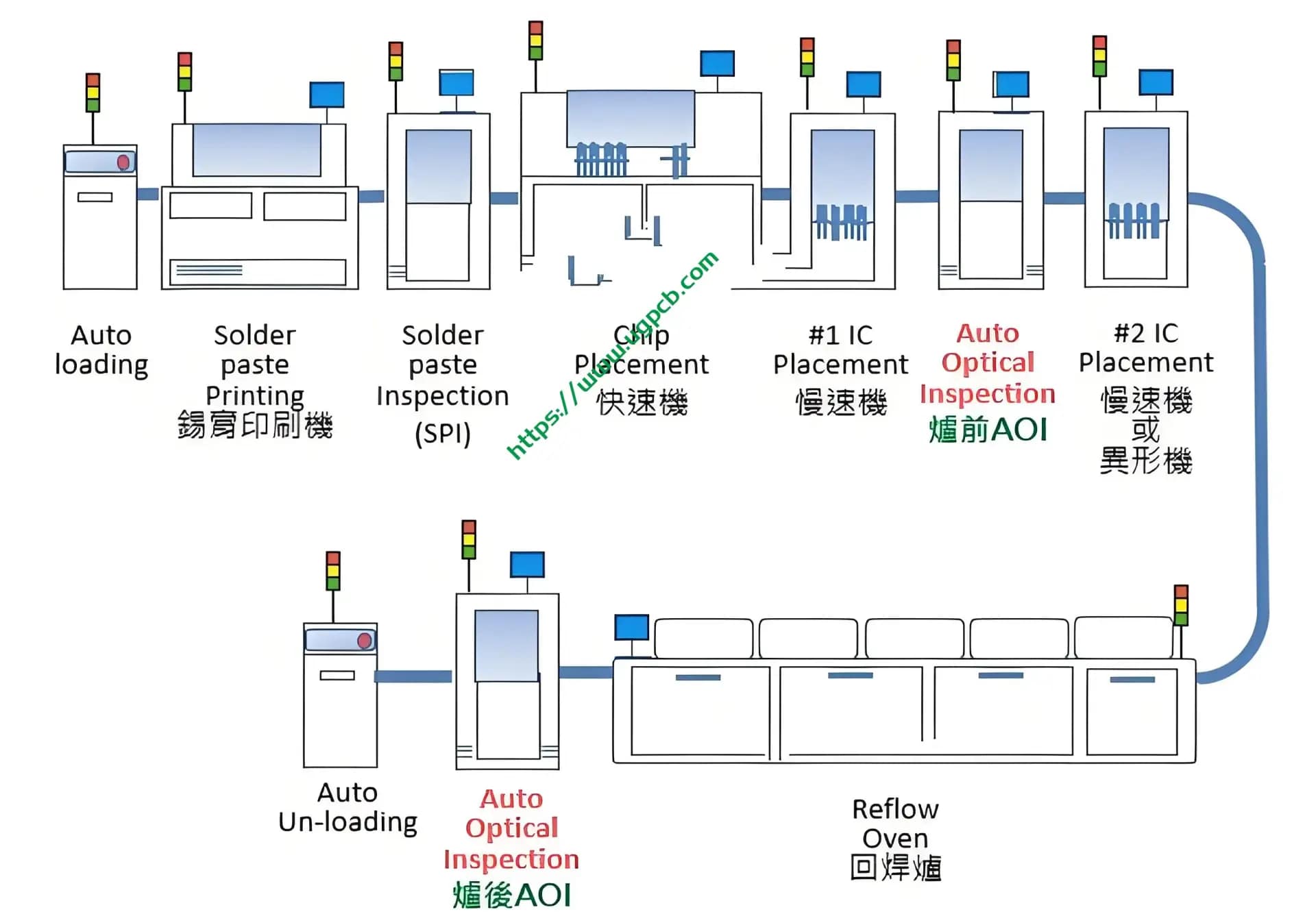
ปัจจุบัน SMT Manufacturing เป็นเทคโนโลยีที่ได้รับความนิยมมากที่สุดและกระบวนการในอุตสาหกรรมการประกอบอิเล็กทรอนิกส์. การไหลของกระบวนการของการผลิต SMT นั้นซับซ้อน, ด้วยการเปลี่ยนแปลงขึ้นอยู่กับผลิตภัณฑ์. อย่างไรก็ตาม, การไหลพื้นฐานโดยทั่วไปรวมถึง: การตรวจสอบวัสดุที่เข้ามา, การเขียนโปรแกรม, การพิมพ์, การตรวจสอบ, การติดตั้ง, การตรวจสอบล่วงหน้า, การบัดกรี, Aoi (การตรวจสอบด้วยแสงอัตโนมัติ) การตรวจจับ, ซ่อมแซม, การทดสอบ, และการชุมนุม.
ท่ามกลางกระบวนการต่าง ๆ ในการผลิต SMT, สามโดดเด่นที่สุด: วางพิมพ์, การติดตั้ง SMT, และ reflow soldering.
วางพิมพ์
การพิมพ์วางเกี่ยวข้องกับการใช้การวางบัดกรีกับ PCB (แผงวงจรพิมพ์). อุปกรณ์และเครื่องมือที่ใช้ในกระบวนการนี้รวมถึง:
- เครื่องพิมพ์: เครื่องพิมพ์อัตโนมัติและกึ่งอัตโนมัติ.
- บัดกรี: วัสดุพิเศษที่ใช้ในการแก้ไขส่วนประกอบลงบน PCB.
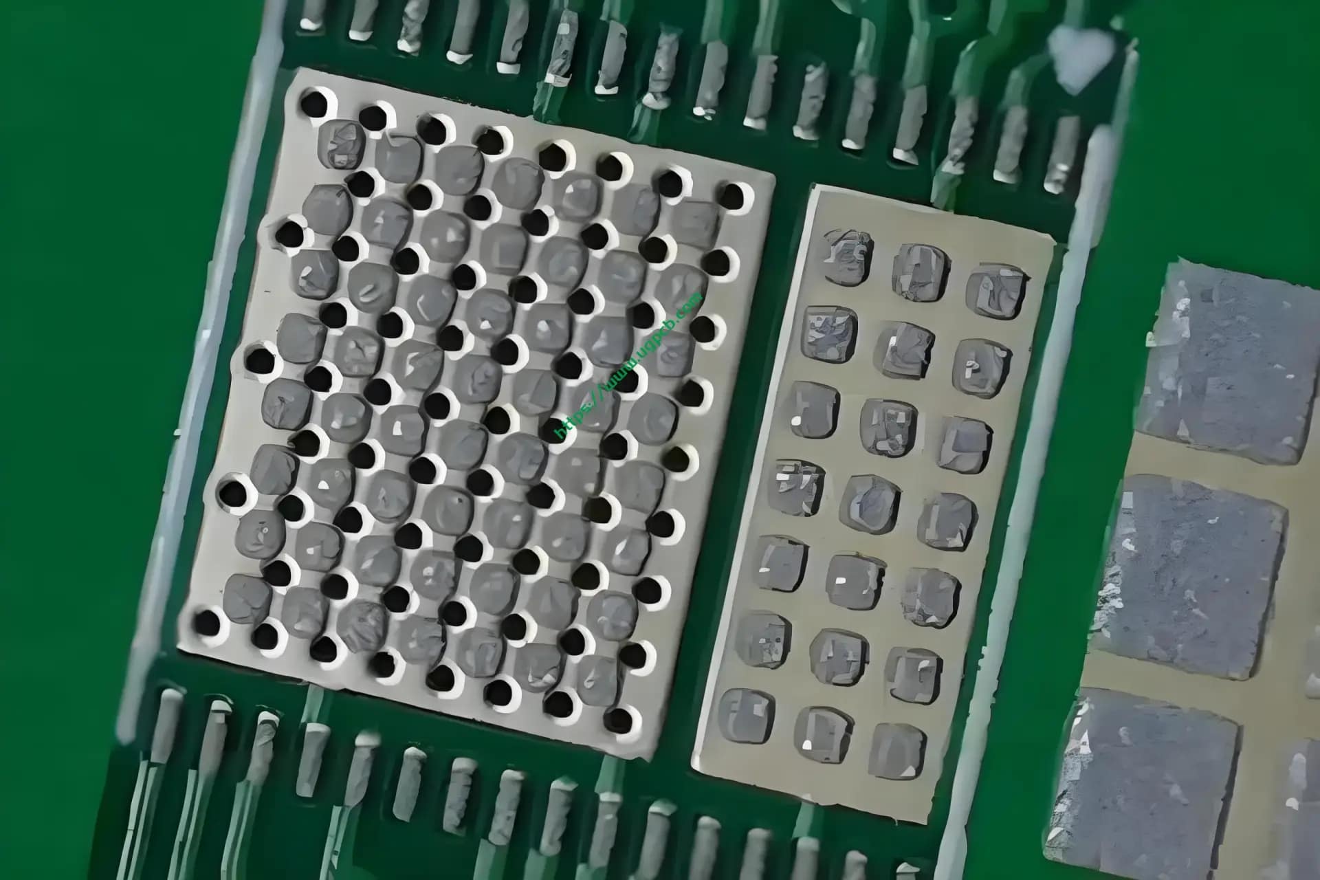
- ลายฉลุ: โดยพื้นฐานแล้วแม่พิมพ์ที่มีตำแหน่งโพรงออกมาซึ่งสอดคล้องกับแผ่นบัดกรีบน PCB, การอนุญาตให้บัดกรีวางผ่านและเคลือบแผ่นรอง. มันเป็นแผ่นเหล็กบาง ๆ ที่แก้ไขด้วยเฟรม, ใช้กันทั่วไปในความหนา 0.10 มม., แตกต่างกันไปตามส่วนประกอบและกระบวนการผลิตของผลิตภัณฑ์ที่แตกต่างกัน. ลายฉลุทำตามไฟล์มาสก์วางในไฟล์ gerber ที่จัดทำโดย r&ทีม D หรือลูกค้า. การเตรียมการนี้มีความสำคัญก่อนการผลิตเนื่องจากคุณภาพของ stencil กำหนดคุณภาพของผลิตภัณฑ์ที่ติดตั้ง. ความสำคัญของลายฉลุมีความชัดเจนโดยเฉพาะอย่างยิ่งในส่วนประกอบที่แม่นยำ, และเครื่องพิมพ์ที่แตกต่างกันมีความหลากหลายในข้อกำหนดของรูรับแสงลายฉลุ. ขึ้นอยู่กับประสบการณ์ส่วนตัว, สำหรับผลิตภัณฑ์ที่มีส่วนประกอบที่มีความแม่นยำเช่น 0.4- สนาม BGA, ขอแนะนำให้ใช้ลายฉลุโดยมืออาชีพของโรงงานผลิต, เนื่องจากไม่มีมาตรฐานที่เข้มงวดสำหรับกระบวนการ. รายละเอียดเป็นที่เข้าใจได้ดีที่สุดโดยวิศวกรกระบวนการในโรงงาน SMT.

การทำงานพื้นฐานเกี่ยวข้องกับการติดตั้ง stencil ในเครื่องพิมพ์, เพิ่มการบัดกรีวางลงในลายฉลุ, การวาง PCB บนแทร็กของเครื่อง, การสแกนจุดทำเครื่องหมายของ PCB และ stencil ด้วยกล้องของเครื่อง, จัดแนวพวกเขา, เพิ่มแพลตฟอร์มการพิมพ์ให้พอดีกับลายฉลุ, จากนั้นใช้ squeegee 45 °ที่เอียงเพื่อขูดบัดกร, โอนไปยังแผ่นบัดกรีบน PCB. สิ่งนี้ทำให้กระบวนการพิมพ์เสร็จสมบูรณ์. หากไม่มีข้อบกพร่อง, มันสมบูรณ์แบบ; ถ้ามี, วิศวกรอุปกรณ์ต้องทำการปรับเปลี่ยนเล็กน้อย. ขึ้นอยู่กับปีของการวิเคราะห์กระบวนการภาคสนาม, การพิมพ์แบบวางเป็นสิ่งสำคัญที่สุดของกระบวนการหลักสามประการในการผลิต SMT, เช่น 70% ข้อบกพร่องของ SMT เกี่ยวข้องกับขั้นตอนนี้.
การติดตั้ง SMT
การติดตั้ง SMT เกี่ยวข้องกับการใช้เครื่องวางตำแหน่งเพื่อติดตั้งส่วนประกอบลงบน PCB ที่พิมพ์ออกมา. คำว่า “การติดตั้ง” ใช้เพราะการบัดกรีมีฟลักซ์, ซึ่งมีความหนืดบางอย่าง, ปล่อยให้มันถือส่วนประกอบก่อนที่จะละลาย.
หลักการของการติดตั้ง SMT นั้นเรียบง่ายและซับซ้อน. มันง่ายเพราะมันวิวัฒนาการมาจากการบัดกรีด้วยตนเอง, โดยที่ส่วนประกอบถูกวางไว้บนแผงวงจรพร้อมแหนบ, ในขณะที่เครื่องวางตำแหน่งใช้หัวดูดสูญญากาศเพื่อแนบส่วนประกอบกับ PCB. มันซับซ้อนเนื่องจากกระบวนการติดตั้งจริงซับซ้อน, เกี่ยวข้องกับอุปกรณ์ที่แม่นยำ. ความก้าวหน้าทางเทคโนโลยีได้เปลี่ยนส่วนประกอบผ่านรูแบบดั้งเดิมให้เป็นส่วนประกอบของพื้นผิว, เพิ่มประสิทธิภาพการผลิตอย่างมีนัยสำคัญและการเปลี่ยนแปลงห่วงโซ่อุปทานของอุตสาหกรรมทั้งหมด.
หลักการทำงานของ SMT เกี่ยวข้องกับการสร้างโปรแกรมตำแหน่งโดยใช้ไฟล์ Gerber, ประสานงานไฟล์, ระเบิด (ใบเรียกเก็บเงิน), และแผนภาพตำแหน่งที่ลูกค้าจัดหาให้. หัวตำแหน่ง (หัวฉีด), เครื่องให้อาหาร, และแทร็กของเครื่องตำแหน่งทำงานร่วมกันเพื่อให้กระบวนการติดตั้งทั้งหมดเสร็จสมบูรณ์.
- หัวฉีด: หัวตำแหน่งมี 12 หัวฉีด, แต่ละแห่งมีศูนย์กลวงที่ใช้การดูดสูญญากาศเพื่อรับส่วนประกอบ.
- เครื่องให้อาหาร: เหล่านี้เป็นอุปกรณ์ฟีดที่, ขึ้นอยู่กับโปรแกรมตำแหน่งที่สร้างขึ้นโดยโปรแกรมเมอร์เครื่องวางตำแหน่ง, ถูกพิมพ์ลงในรายการสถานี. ผู้ประกอบการติดตั้งส่วนประกอบบนตัวป้อนตามลำดับรายการสถานี. เครื่องป้อนถูกจัดเรียงบนเครื่องวางตำแหน่ง, ขับเคลื่อน, และขับเคลื่อนด้วยเกียร์เพื่อเลื่อนเทปส่วนประกอบ. โปรแกรมสั่งให้หัวฉีดดูดที่ระบุเพื่อย้ายไปยังตำแหน่งที่กำหนดเพื่อรับส่วนประกอบและวางไว้ที่พิกัดที่ระบุ.
ข้อควรระวัง:
- ส่วนประกอบที่มีขนาดแตกต่างกันต้องการหัวฉีดและตัวป้อนขนาดต่างกัน.
- เนื่องจากหัวฉีดดูดใช้รถปิคอัพสูญญากาศ, มันเป็นสิ่งสำคัญเพื่อให้แน่ใจว่าพื้นผิวส่วนประกอบแบนและไม่รั่วสูญญากาศระหว่างการออกแบบและการผลิตตัวอย่าง. สำหรับส่วนประกอบพิเศษเช่นเสาอากาศติดต่อหรืออุปกรณ์กลวงออก, ซัพพลายเออร์อาจต้องเพิ่ม “หมวก” หรือใช้เทปกาวอุณหภูมิสูงกับพื้นผิว.
- หลีกเลี่ยงการใช้วัสดุจำนวนมาก.
การบัดกรี
หลังจากวางการพิมพ์และการติดตั้ง, ขั้นตอนต่อไปคือการบัดกรี reflow. เมื่อติดตั้งส่วนประกอบทั้งหมด, PCB ถูกส่งไปยังสายพานลำเลียงโดยเครื่องวางตำแหน่งสำหรับการตรวจสอบด้วยตนเองหรือการตรวจสอบ AOI ล่วงหน้าเพื่อตรวจสอบข้อบกพร่องในการติดตั้งใด ๆ. หากไม่มีปัญหา, PCB สามารถเข้าสู่เตาอบรีดว์.
หลายคนอาจไม่รู้อะไร “รีด” หมายถึงการบัดกรี reflow. ไม่ได้อ้างถึงการบัดกรีที่ไหลจากที่หนึ่งไปยังอีกที่หนึ่ง. การบัดกรี reflow มาจาก “การบัดกรี,” ที่ไหน “รีด” หมายถึงการเปลี่ยนการบัดกรีแบบเม็ดเป็นสถานะของเหลวแล้วทำให้มันแข็งเป็นโลหะผสม. เตาอบรีดว์เป็นเหมือน “เตาอบ” ด้วยสายพานลำเลียงที่คล้ายกับห่วงโซ่จักรยาน. เป็นเตาอบสี่เหลี่ยมที่ขนส่ง PCBS, ร้อนและละลายบัดกรีวาง, และทำให้ส่วนประกอบของแผ่นบัดกรีของ PCB แข็งตัวให้แข็งตัว. เตาอบรีดว์มีอุปกรณ์อากาศร้อนแบ่งออกเป็นหลายโซนอุณหภูมิ, ค่อยๆร้อนขึ้น. กระบวนการสามารถอธิบายได้โดยใช้เส้นโค้งที่มีสี่โซนสำคัญ.
- เปิดโซนร้อน: อุ่น PCB และส่วนประกอบ, ส่วนใหญ่หมายถึงเอฟเฟกต์ความร้อนของโซนทำความร้อนครั้งแรกถึงสามโซนของเตาอบรีฟว์. การอุ่นอุ่นที่สูงขึ้นบรรลุความสมดุลทางความร้อนสำหรับวัสดุที่จะบัดกรี, การอนุญาตให้บัดกรีวางอยู่, และส่วนประกอบเช่นฟลักซ์เพื่อระเหยอย่างเหมาะสม, ปูทางไปสู่การบัดกรีที่ดีในภายหลัง.
- โซนแช่: กำจัดออกไซด์ของพื้นผิวและทำให้การบัดกรอยู่กับการใช้งาน, ด้วยการบัดกรีในสถานะกึ่งโมลเทน, สอดคล้องกับห้า, ที่หก, และโซนทำความร้อนที่เจ็ดของเตาอบรีดว์.
- เขต: หรือที่รู้จักกันในชื่อเขตบัดกรี, มันเป็นพื้นที่ที่ร้อนแรงที่สุดในเตาอบรีดว์, ถึงจุดหลอมเหลวของบัดกรี, โดยทั่วไปจะอยู่ที่ประมาณ 220 ° C สำหรับการบัดกรี, ยั่งยืนเกี่ยวกับ 40 ไม่กี่วินาที.
- โซนระบายความร้อน: ค่อยๆเย็นลงจากจุดหลอมเหลวไปที่ประมาณ 50 ° C, การสร้างข้อต่อประสานโลหะผสม.
สิ่งนี้ทำให้กระบวนการรีดกลับเสร็จสมบูรณ์, ซึ่งมักจะใช้เวลาประมาณหกนาที.
บทสรุป
บทความนี้ให้คำอธิบายและคำอธิบายของกระบวนการหลักสามประการของการผลิต SMT: การพิมพ์, การติดตั้ง, และ reflow soldering. ด้วยข้อมูลนี้, บุคลากรที่เกี่ยวข้องควรมีความเข้าใจที่ลึกซึ้งยิ่งขึ้นเกี่ยวกับขั้นตอนสำคัญเหล่านี้ในการผลิต SMT.
 โลโก้ UGPCB

