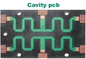
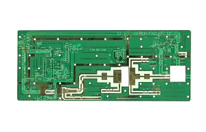
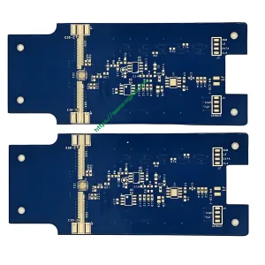
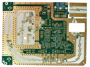
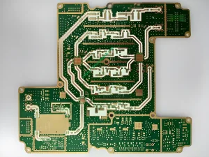
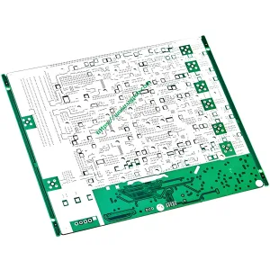
rogers duroid 5880, rogers duroid 5870 Microwave Laminates Non-woven Glass Microfiber Reinforced PTFE Composites
FEATURES AND BENEFITS:
Lowest electrical loss for reinforced PTFE material.
• Provides low insertion loss.
• Able to design high Q circuits.
Low moisture absorption.
• No special storage requirements.
• Reduces effects of moisture on
electrical loss.
Isotropic.
• Improved performance on filters and directional couplers.
Uniform electrical properties over frequency.
• Repeatable designs.
• Suitable for very broadband
การใช้งาน.
Excellent chemical resistance.
• Immune to effects of typical
processing chemicals.
rogers duroid 5880
Typical Applications:
• Commercial Airline Telephony PCB
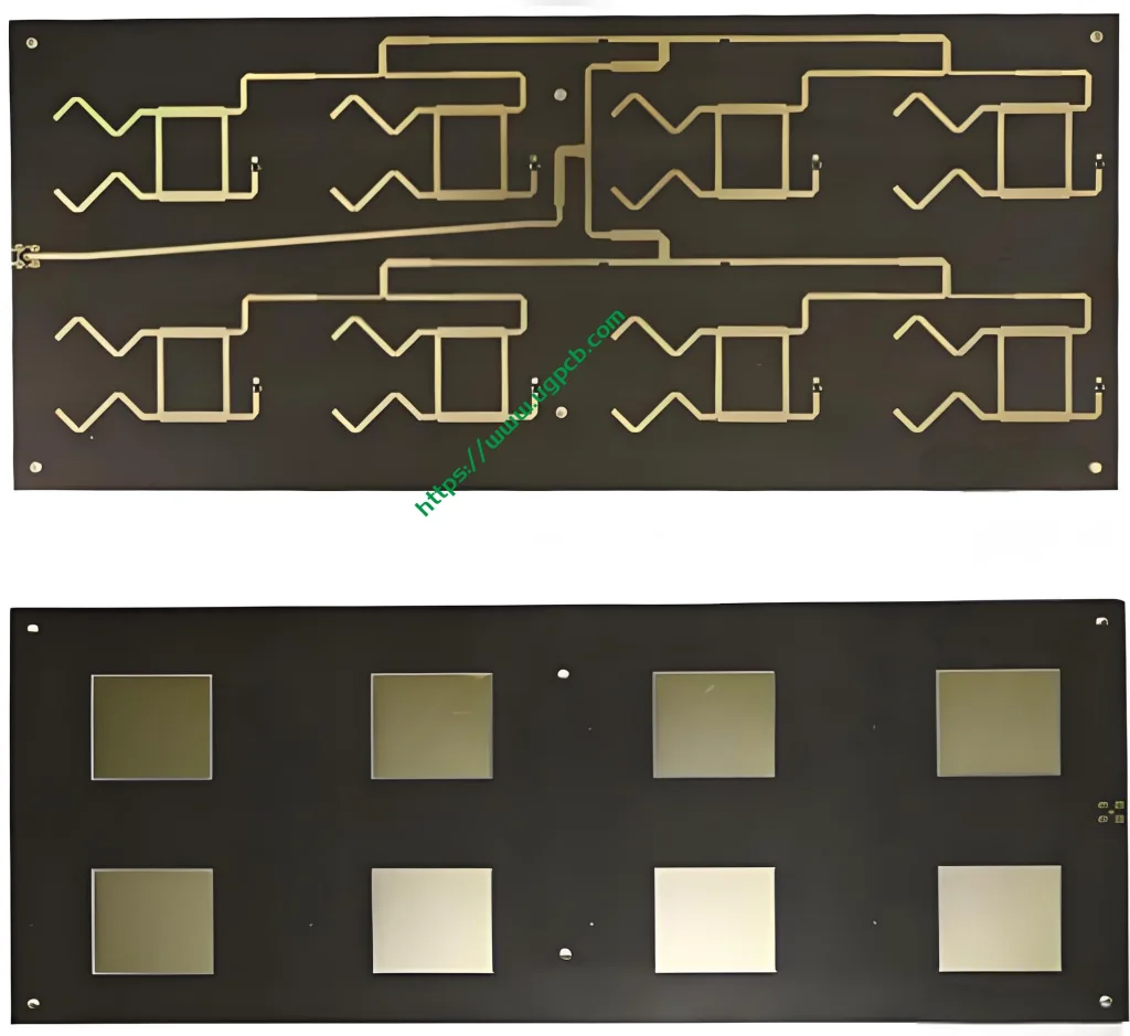
• Microstrip and Stripline Circuits PCB
• Millimeter Wave Applications PCB
• Military Radar Systems PCB
• Missile Guidance Systems PCB
• Point-to-Point Digital Radios PCB
• Antennas PCB
For microwave level high frequency circuit, each corresponding stripline on PCB forms a microstrip line (asymmetric type) with the grounding plate. For PCB with more than two layers, it can form a microstrip line and a stripline (symmetrical microstrip transmission line). Different microstrip lines (double sided PCB) or stripline (multi-layer PCB) form coupling microstrip lines with each other, thus forming various complex four port network, thus forming various characteristics of microwave level circuit PCB. It can be seen that the microstrip transmission line theory is the design basis of microwave high frequency circuit PCB.
The characteristic impedance ZC of air microstrip line is only related to its structure parameters w and H. The effective permittivity ε e is not only related to W and h, but also to the relative permittivity of dielectric.
By using the above formula, the characteristic impedance ZC of microstrip lines with different w / h can be obtained when the dielectric constant of substrate is ε R, and the value of W / h can also be calculated in the opposite way.
The loss of microstrip line mainly includes dielectric loss of substrate, ohmic loss of conductor and radiation loss. The first two losses are major. As long as the microstrip line size
If the size is appropriate, the dielectric constant of the substrate is high, and the radiation loss can be ignored. In order to reduce the radiated interference, the specification of microstrip line and substrate material should be considered first.
The loss will lead to the attenuation of the signal in the microstrip line. The attenuation coefficient α is usually used to represent the attenuation characteristic. The attenuation of microstrip line is mainly determined by dielectric attenuation constant, α D and ohmic attenuation constant α C

Characteristic impedance of microstrip line
α = α D + α C α is the logarithm of amplitude attenuation of signal (voltage or current) per unit length of microstrip line.
Rogers duroid 5880 is a filled PTFE composite material designed for precision stripline and microstrip circuit applications. The unique filler makes the material have the characteristics of low density and light S-shape to meet the requirements of off-frequency performance and sensitive application to J5.
 โลโก้ UGPCB
